Connector

a technology of connecting rods and connectors, applied in the direction of connecting rods, electrical appliances, coupling devices, etc., can solve the problem of increasing manufacturing costs, and achieve the effect of not increasing the type of covers

Inactive Publication Date: 2008-08-07
SUMITOMO WIRING SYST LTD
View PDF13 Cites 19 Cited by
  • Summary
  • Abstract
  • Description
  • Claims
  • Application Information

AI Technical Summary

Benefits of technology

[0015]The invention provides the effect of diversifying the pull-ou...

Problems solved by technology

The large number of molds creates inventory ma...

Method used


Image

  • Connector
  • Connector
  • Connector

Examples


Embodiment Construction

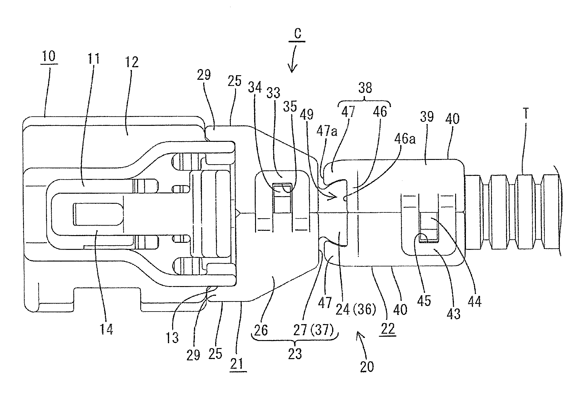
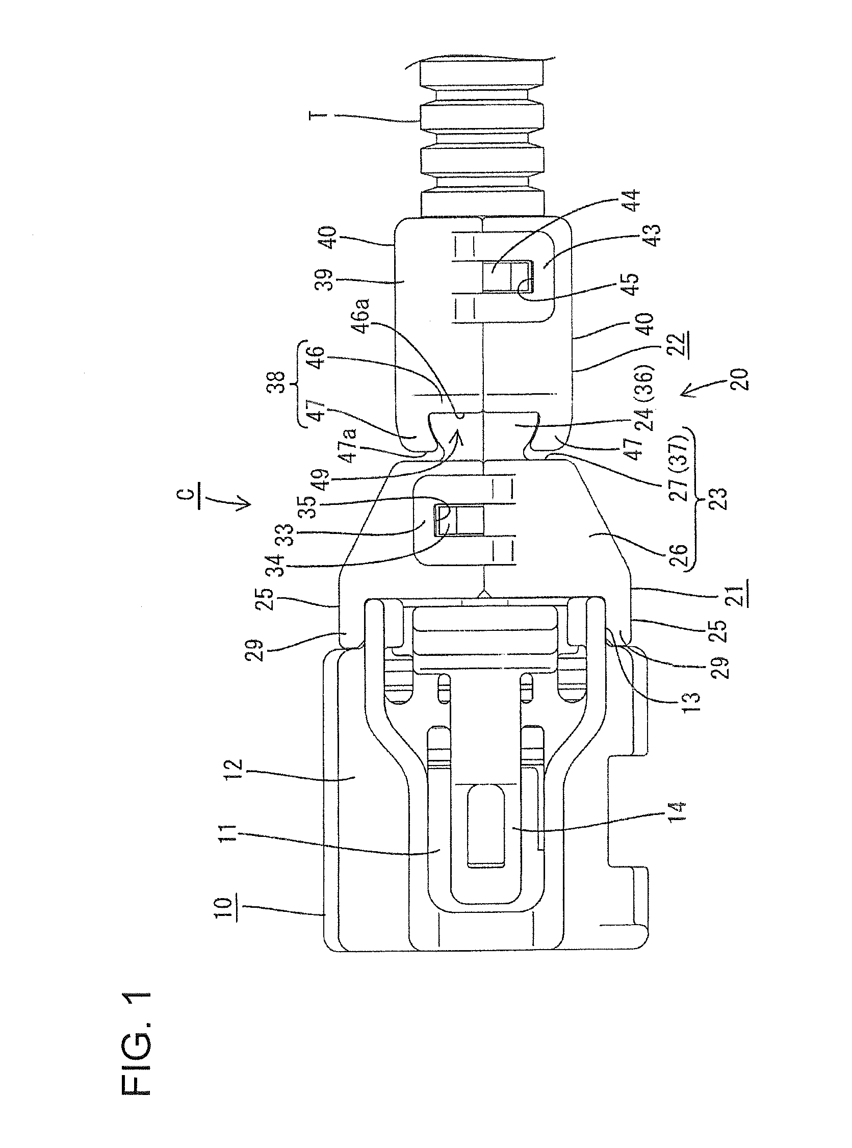
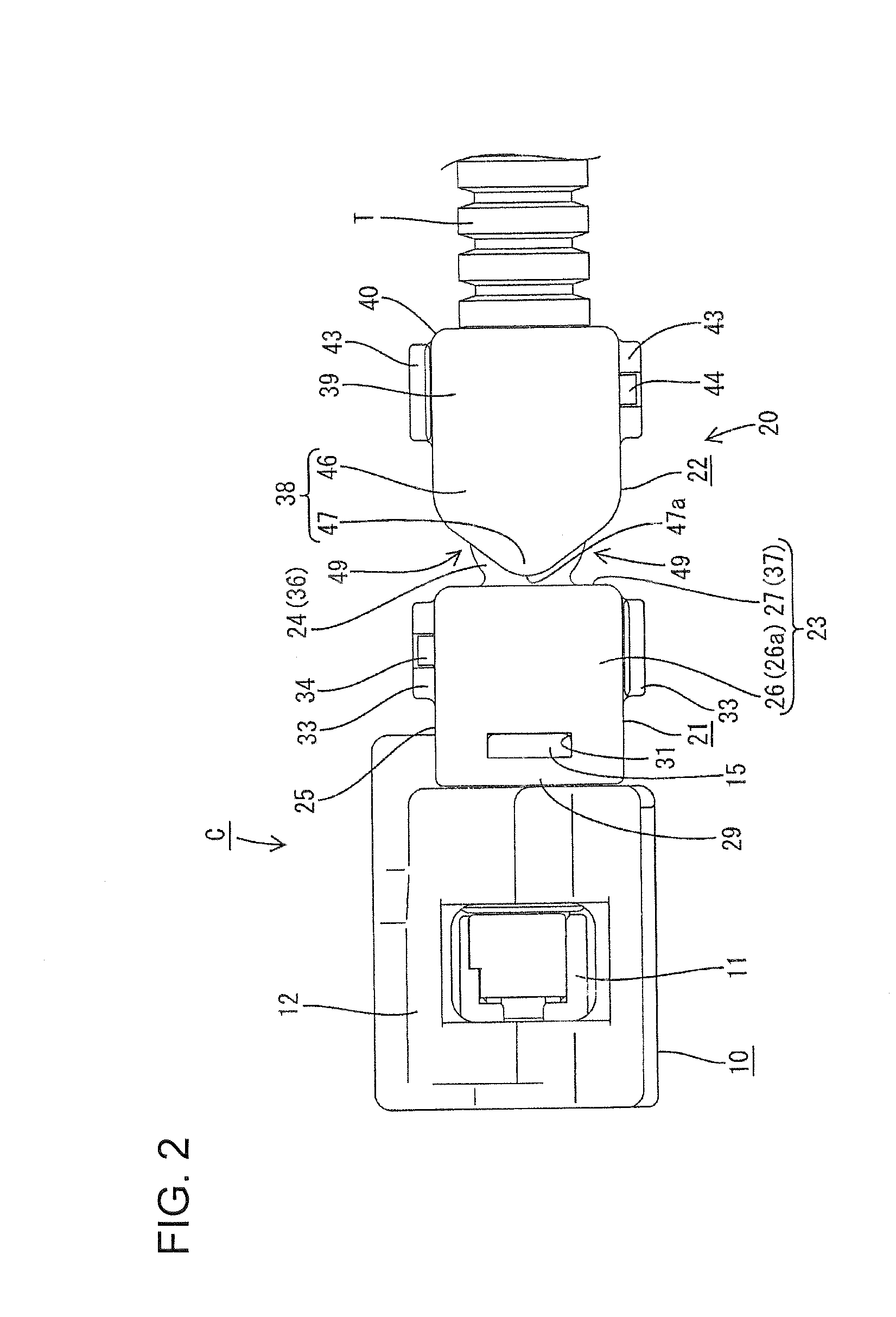
[0045]A female connector in accordance with a first embodiment of the invention is identified by the letter C in FIGS. 1 through 19. The female connector C is intended for use in a wire harness in a car. In the following description, the fit-on end of the connector C (left side in FIGS. 1 and 2) is the “forward” end and the side opposite to the fit-on side (right side in FIGS. 1 and 2) is the “rearward” end. FIGS. 2 and 4 are set as the reference in a vertical direction.

[0046]As shown in FIGS. 1 through 4, the connector C includes a housing 10. Terminal fittings (not shown) are connected with the ends of electric wires W and are accommodated in the housing 10 so that the wires W are pulled out rearward from the housing 10. A cover assembly 20 is mounted at a rear portion of the housing 10 and surrounds the wires W. Part of the wires W rearward from the cover assembly 20 are surrounded with a bellows-shaped cylindrical corrugate tube T made of flexible synthetic resin. Thus, the cove...


PUM


Abstract

A connector has a housing (10) accommodating terminal fittings connected with wires (W). A fixed cover (21) is mounted on the housing (10) and surrounds the wires (W) pulled out of the housing (10) and a movable cover (22) is mounted on an end of the fixed cover (21) opposite the end that is mounted on the housing (10). The fixed cover (21) has a receiving part (24) with a spherical peripheral surface (36). The movable cover (22) has a rotation-holding part (38) fit on an outer side of the receiving part (24). The rotation-holding part (38) is rotatable relative to the receiving part (24) about an axis of the housing (10) and about a rotational axis orthogonal to the axis of the housing (10).

Description

BACKGROUND OF THE INVENTION[0001]1. Field of the Invention[0002]The invention relates to a connector.[0003]2. Description of the Related Art[0004]U.S. Pat. No. 5,908,327 discloses a connector for a wire harness of a car. The connector has a housing that accommodates terminal fittings connected respectively with wires of the wiring harness. A cover is mounted at a rear portion of the housing and surrounds the electric wires pulled out of a rear surface of the housing.[0005]The conventional connector has a specified pull-out direction for the electric wires. However, the pull-out direction of the wires may have to be changed in accordance with the mounting place and the mounting posture of the housing. Hence, a cover suitable for each pull-out direction of the electric wires is required. Each unique cover requires a dedicated mold, and it is necessary to prepare a large number of molding dies for producing the cover. The large number of molds creates inventory management problems and ...

Claims


Application Information

Patent Timeline
IPC IPC(8): H01R13/58
CPCH01R13/5841
Inventor TSUJI, TAKESHI
Owner SUMITOMO WIRING SYST LTD
Why Eureka
Try Eureka