

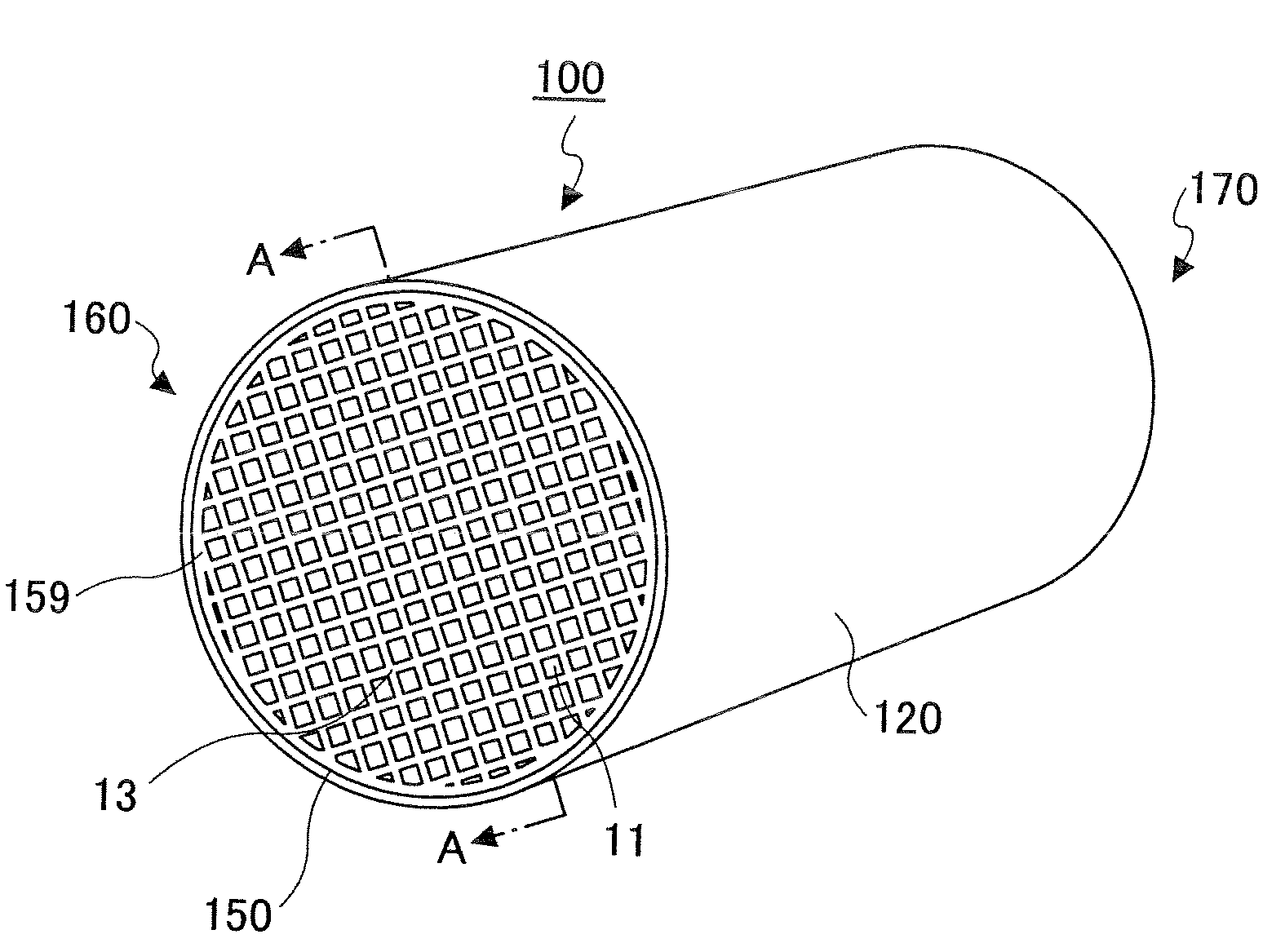
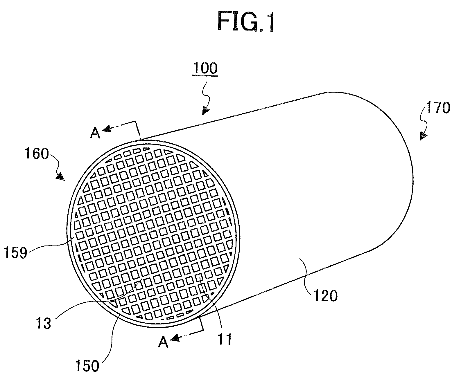
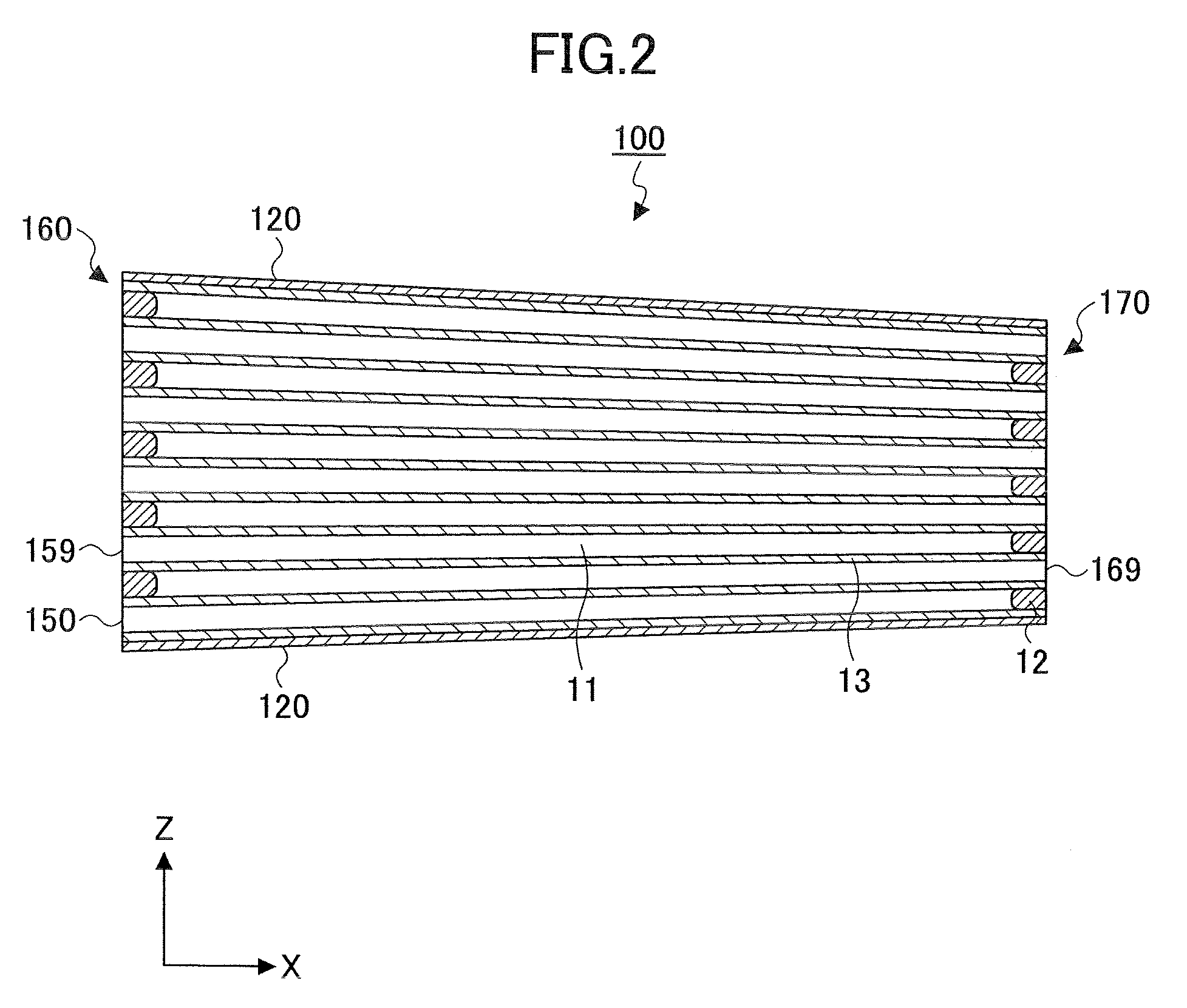
Honeycomb structural body and exhaust gas treating apparatus
- Summary
- Abstract
- Description
- Claims
- Application Information
AI Technical Summary
Problems solved by technology
Method used
Image

Examples
example 1
Practical Example 1
Fabrication of Joint Type Honeycomb Structural Body
[0103]First, 40% by weight of γ alumina particles (average particle size 2 μm), 10% by weight of silica-alumina fiber (average fiber diameter 10 μm, average fiber length 100 μm, aspect ratio 10), and 50% by weight of silica sol (solid concentration 30% by weight) were mixed together. Then, 6 pts.wt. of methylcellulose functioning as an organic binder and small amounts of a plasticizer and a lubricant were added to 100 pts.wt. of the resultant mixture. This mixture was further mixed and kneaded to produce a mixed composition. This mixed composition was subjected to extrusion molding by using an extrusion molding apparatus to obtain a raw molded body.
[0104]Next, the raw molded body was sufficiently dried using a micro dryer and a hot air dryer, and was degreased by being kept in an atmosphere of 400° C. for two hours. Then, the molded body was fired by being kept in an atmosphere of 800° C. for two hours. Accordingl...
example 2
Practical Example 2
[0113]A joint type honeycomb structural body was fabricated and arranged in the exhaust gas treating apparatus by the same method as that of practical example 1. However, in practical example 2, the coat layer paste was applied in such a manner that its thickness gradually decreases from the first end face (5.0 mm thick) to the second end face (0.5 mm thick). Thus, the taper rate P of the final honeycomb structural body was 3%.
[0114]A regeneration test was performed by the same method as that of practical example 1, with the exhaust gas treating apparatus equipped with this honeycomb structural body. After performing the test, it was confirmed that the honeycomb structural body was not broken around its second end surface.
example 3
Practical Example 3
[0115]A joint type honeycomb structural body was fabricated and arranged in the exhaust gas treating apparatus by the same method as that of practical example 1. However, in practical example 3, the coat layer paste was applied in such a manner that its thickness gradually decreases from the first end face (6.5 mm thick) to the second end face (0.5 mm thick). Thus, the taper rate P of the final honeycomb structural body was 4%.
[0116]A regeneration test was performed by the same method as that of practical example 1, with the exhaust gas treating apparatus equipped with this honeycomb structural body. After performing the test, it was confirmed that the honeycomb structural body was not broken around its second end surface.
PUM
| Property | Measurement | Unit |
|---|---|---|
| Fraction | aaaaa | aaaaa |
| Thickness | aaaaa | aaaaa |
| Thickness | aaaaa | aaaaa |
Abstract
Description
Claims
Application Information