Generic pick-up horn for high power thermal vacuum testing of satellite payloads at multiple frequency bands and at multiple polarizations

a generator pick-up horn and high-power thermal vacuum technology, applied in waveguide horns, instruments, measurement devices, etc., can solve the problems of affecting the accuracy of payload testing, slow approach, and inability to test payload operations at full power in vacuum environmen

Inactive Publication Date: 2008-08-14
LOCKHEED MARTIN CORP
View PDF30 Cites 14 Cited by
  • Summary
  • Abstract
  • Description
  • Claims
  • Application Information

AI Technical Summary

Benefits of technology

[0008]As is described in further detail herein, aspects and embodiments of the present invention can accordingly provide for high power TVAC testing of satellite payloads operating over various transmission spectrums or bands including, but not limited to, the X-band, Ku-band, and Ka-band (e.g., operating from 7.0 GHz to 21.0 GHz). Such pick-up horn techniques can be used for receiving, absorbing, and cooling high power from the satellite payloads and flight horns, while allowing complete performance tests of all the payload transponders through their feed horns and thermal validation of the payload simultaneously without breaking the vacuum. Such techniques can further provide good return loss with the flight horns to ensure minimal reflected power back into the horns, while minimizing the RF leakage into the spacecraft.
[0012]A further aspect of the present invention provides a method of testing one or more spacecraft payload antenna feeds. The method can include configuring one or more pick-up horns of the present invention in proximity to one or more antenna feeds of a spacecraft payload. Each pick-up horn is positioned relative to the corresponding payload antenna to receive the radiated power produced by the antenna feed. Physical contact between each pick-up horn and corresponding antenna feed is avoided. The payload, including payload antenna / antenna feed(s), and the one or more pick-up horns are placed in a thermal vacuum chamber. The one or more antenna feeds of the payload are energized to produce radiated RF power. The radiated RF power is received with the one or more pick-up horns. The temperature of the one or more pick-up horns is monitored. The RF drive signals provide to the one or more antenna feeds are controlled to reduce the radiated power of the antenna feeds in the event the temperature one or more of the pick-up horns exceeds a specified value. The temperature of the payload can be adjusted in the vacuum for thermal testing.

Problems solved by technology

Because the payloads of spacecraft frequently operate at very high power (e.g., radiating antennas operating at 2000 W or more), testing payload operations at full power in a vacuum environment presents a number of challenges.
Because these absorber boxes are so large, they frequently prevent all antennas on a spacecraft from being tested at the same time.
This approach is very slow, as the process of de-pressurizing and re-pressurizing the TVAC chamber and testing the spacecraft can take up to two or three months.
To attach the waveguides, it is necessary to decouple the radiating horn antennas from the spacecraft, which can negatively affect the accuracy of the payload testing.
Because waveguides are sensitive to the polarization of radiation, working best with linearly polarized radiation, there may be significant return loss (i.e., reflection of incident radiation) with antennas that emit elliptically polarized radiation.
Moreover, the ceramic window through which the waveguide directs the radiation presents a danger of vacuum compromise, which can result in damage to the spacecraft.

Method used


Image

  • Generic pick-up horn for high power thermal vacuum testing of satellite payloads at multiple frequency bands and at multiple polarizations
  • Generic pick-up horn for high power thermal vacuum testing of satellite payloads at multiple frequency bands and at multiple polarizations
  • Generic pick-up horn for high power thermal vacuum testing of satellite payloads at multiple frequency bands and at multiple polarizations

Examples


Embodiment Construction

[0035]In the following detailed description, numerous specific details are set forth to provide a full understanding of the present invention. It will be apparent, however, to one ordinarily skilled in the art that the present invention may be practiced without some of these specific details. In other instances, well-known structures and techniques have not been shown-in detail to avoid unnecessarily obscuring the present invention.

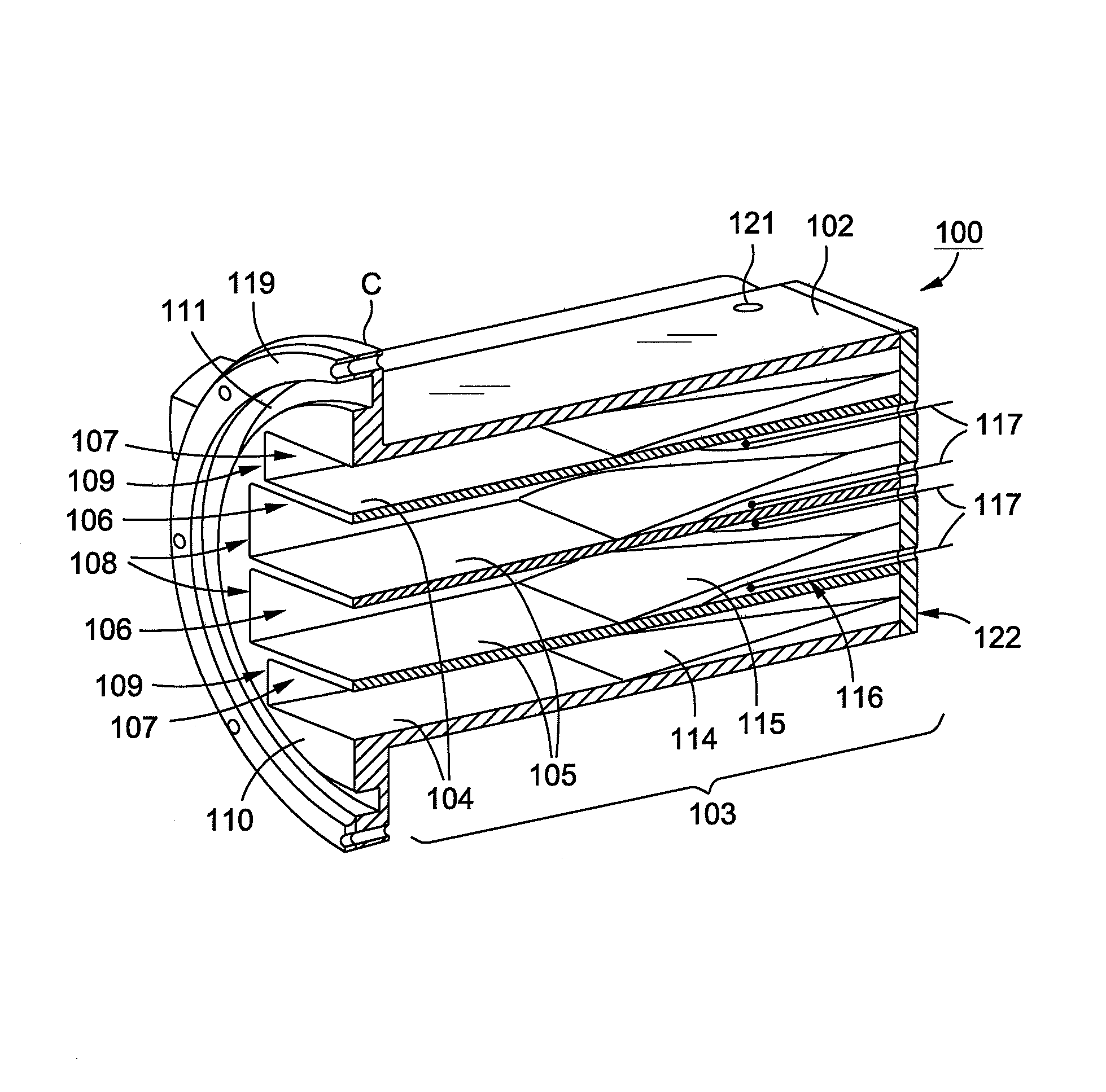
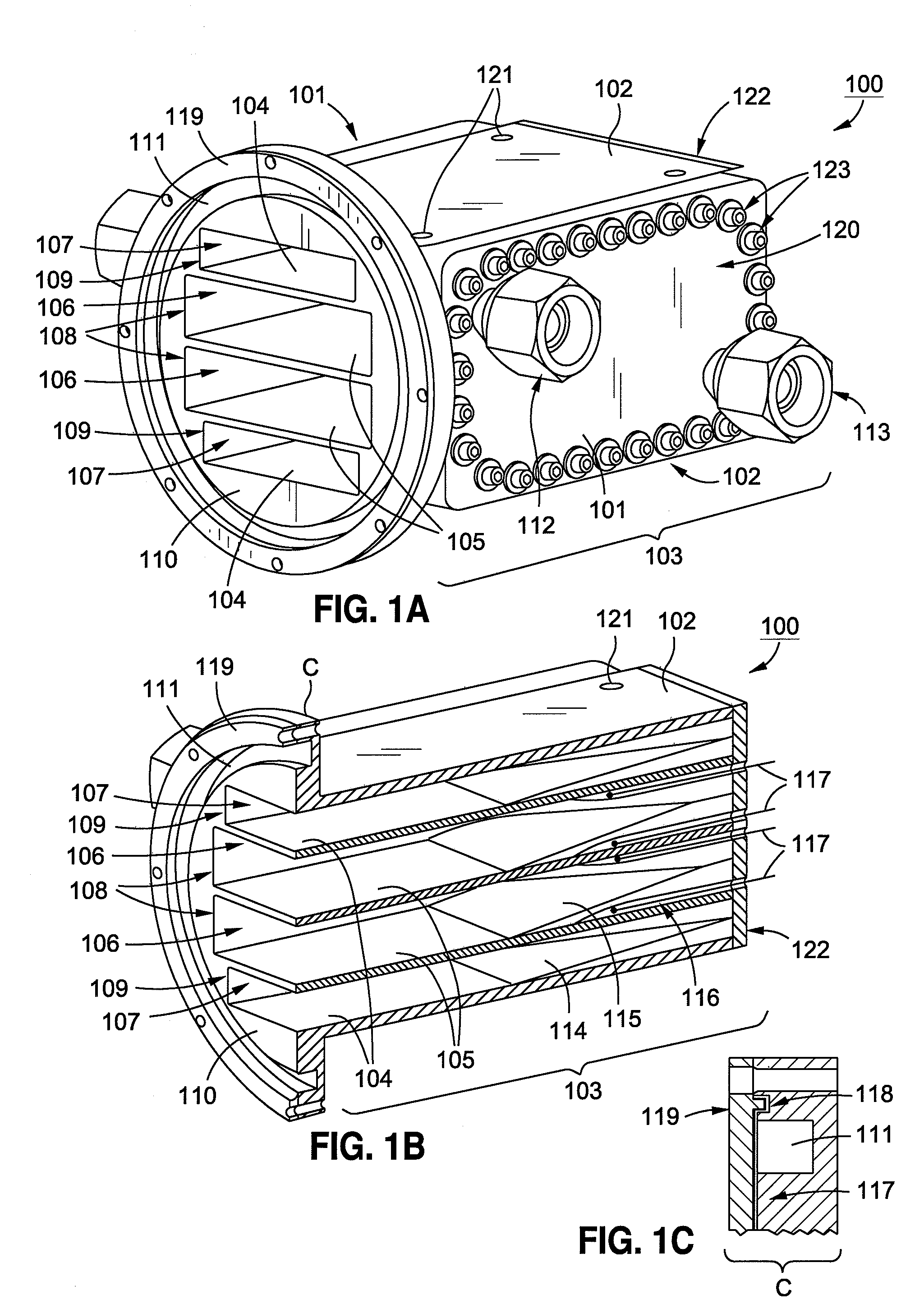
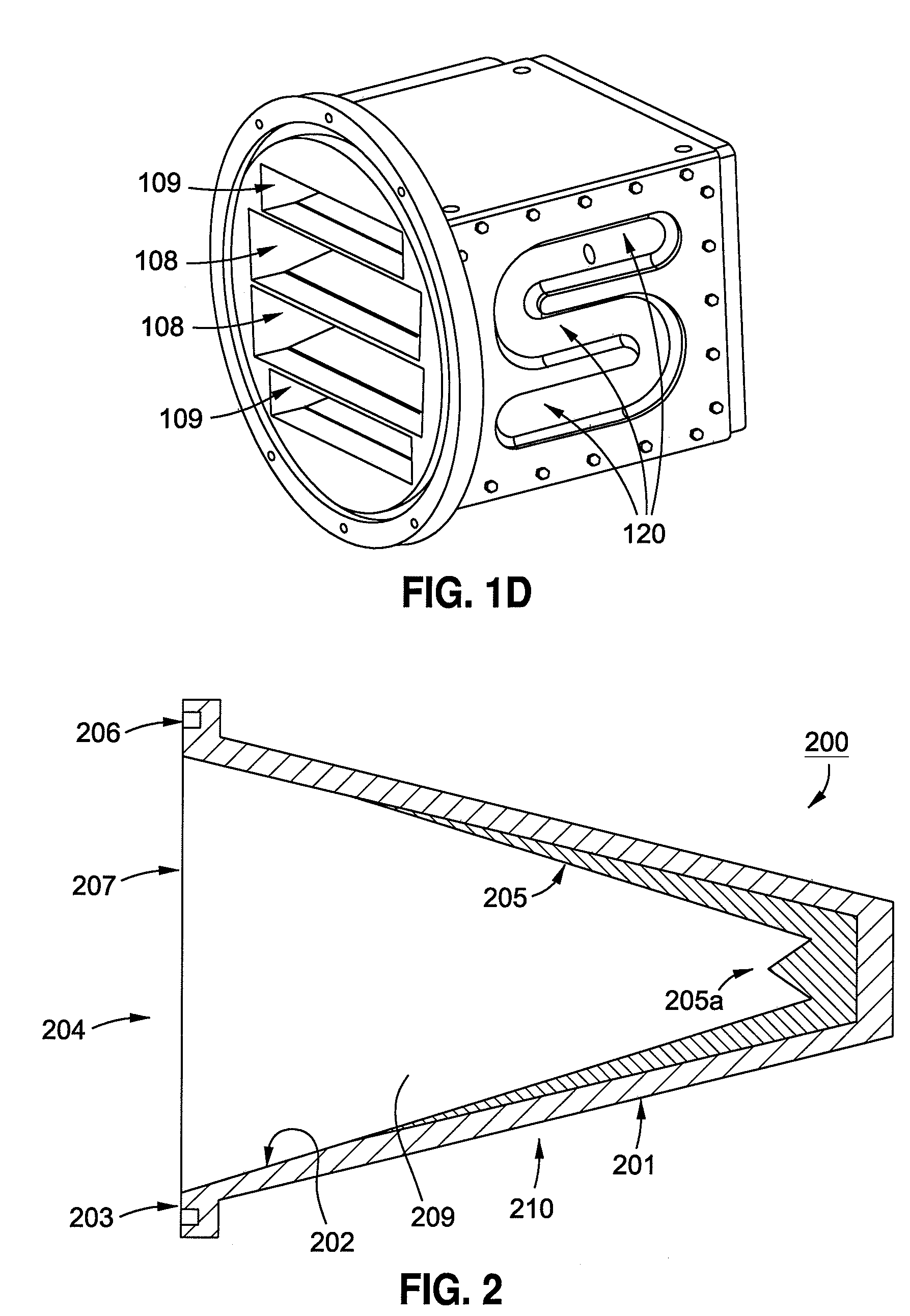
[0036]The present invention provides systems, methods, and apparatus that utilize one or more pick-up horns for use during high-power thermal vacuum testing (TVAC) of a spacecraft payload. Such spacecraft payloads can include various transmitting antennas operational over communications bands including those used for satellite to ground communications links. The payload antennas can include those operating in various microwave regimes including, but not limited to, X-band, Ku-band and Ka-band; other frequencies and bands may also be accommodated. The payl...


PUM

PropertyMeasurementUnit
poweraaaaaaaaaa
boiling pointaaaaaaaaaa
temperatureaaaaaaaaaa

Abstract

Methods, systems, and apparatus are disclosed for high power thermal vacuum testing of satellite payloads using pick-up horns. Such pick-up horns can include at least one outer metal wall forming a metal body and at least one interior surface disposed in the metal body, forming at least one chamber in the metal body. The pick-up horn further includes a front metal surface disposed at a front end of the metal body, having at least one opening corresponding to the at least one chamber, and at least one high-power absorbing load disposed within the at least one chamber and in contact with the at least one interior surface. A pick-up horn may further include a serpentine coolant path disposed within the metal body between an outer surface of the at least one outer metal wall and the at least one high-power absorbing load. Related systems and methods are described.

Description

RELATED APPLICATIONS[0001]This application is a continuation-in-part of U.S. application Ser. No. 11 / 446,974 filed 6 Jun. 2006, which claims the benefit of U.S. Provisional Application Ser. No. 60 / 758,940 filed 12 Jan. 2006, the contents of both of which are incorporated herein by reference in their entireties; further, this application claims the benefit of U.S. Provisional Application Ser. No. 60 / 907,476 filed 3 Apr. 2007, the content of which is incorporated herein by reference in its entirety.FIELD OF THE INVENTION[0002]The present invention generally relates to the testing of satellites and, more particularly, relates to the high-power thermal vacuum testing of satellite payloads at multiple frequency bands and at multiple polarizations.BACKGROUND OF THE INVENTION[0003]Prior to launch, spacecraft are regularly subjected to thermal vacuum testing to ensure that their payloads function as intended in the vacuum of space. Because the payloads of spacecraft frequently operate at ve...

Claims


Application Information

Patent Timeline
Patent Type & Authority Applications(United States)
IPC IPC(8): H01Q13/02G01R29/08
CPCG01R29/10H01Q17/00H01Q13/02H01Q1/02
Inventor RAO, SUDHAKAR K.LEE-YOW, CLENCYVENEZIA, PHILIPMACGREGOR, MARK W.
Owner LOCKHEED MARTIN CORP
Why Eureka
Try Eureka