Adjustable antenna

An antenna and bridge technology, applied in the field of adjustable antenna, can solve the problems of narrow adjustable range, inflexible adjustment, impedance change, etc., to achieve the effect of large adjustment range, change adjustment range, and improve radiation efficiency

Inactive Publication Date: 2016-06-01
HYTERA COMM CORP
View PDF11 Cites 5 Cited by
  • Summary
  • Abstract
  • Description
  • Claims
  • Application Information

AI Technical Summary

Problems solved by technology

Defects of this technology: the adjustable range is narrow, and the return loss of each frequency point is not easy to control; if it is used behind the power amplifier, adjusting the capacitance of the varactor diode 21 will cause the impedance at both ends to change, resulting in unstable operation of the power amplifier (such as self-excited)
Defects of this technology: the adjustment is not flexible enough, cannot be adjusted continuously, and the step is too large

Method used


Image

  • Adjustable antenna
  • Adjustable antenna
  • Adjustable antenna

Examples


Embodiment Construction

[0019] The following will clearly and completely describe the technical solutions in the embodiments of the present invention with reference to the drawings in the embodiments of the present invention. The above description is a preferred embodiment of the present invention, and it should be pointed out that for those skilled in the art, without departing from the principle of the present invention, some improvements and modifications can also be made, and these improvements and modifications are also considered Be the protection scope of the present invention.

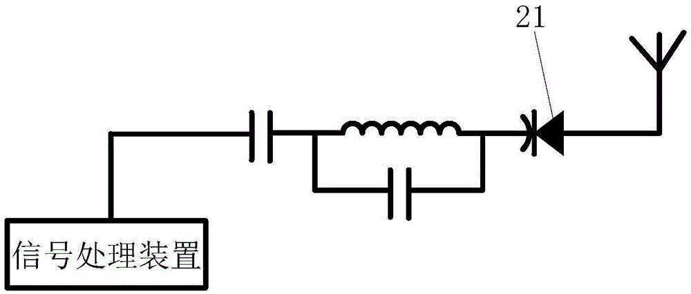
[0020] An adjustable antenna provided by an embodiment of the present invention includes an antenna, a matching inductor, and a phase shifter; the input end of the phase shifter is connected to the antenna, and the microwave signal received by the antenna is input, and the output end of the phase shifter outputs a transformed After the microwave signal, the matching circuit 2 is connected between the input terminal of...


PUM


Abstract

The invention provides an adjustable antenna. The adjustable antenna comprises an antenna, a matching inductor and a phase shifter, wherein the input end of the phase shifter is connected with the antenna and inputs a microwave signal received by the antenna, the output end of the phase shifter outputs the microwave signal after conversion, and the matching inductor is connected between the input end of the phase shifter and ground. By the adjustable antenna, the radiation efficiency of the antenna is improved better, a wide adjustable range can be acquired, continuous adjustment can be achieved, and the adjustable antenna is flexible and convenient. Moreover, if the characteristic impedance of the phase shifter is changed, the adjustment range can be changed, different antennas can be matched, and return loss can be amplified.

Description

technical field [0001] The invention relates to the field of antennas, in particular to an adjustable antenna. Background technique [0002] Most of the antennas currently on the market are non-adjustable, which means that the return loss of the antenna is fixed. When the transmit / receive frequency has the best return loss (large), the radiation efficiency of the antenna will be the highest, while When the return loss is relatively poor (small), most of the power is reflected back, resulting in low radiation efficiency of the antenna. [0003] refer to figure 1 as shown, figure 1 It is the first antenna with adjustable frequency band in the prior art. By changing the capacitance value of the varactor diode 21 to change the resonant frequency in the matching resonant circuit, so as to realize the movement of the bandwidth and adjust the return loss within a certain range Function. Defects of this technology: the adjustable range is narrow, and the return loss of each freq...

Claims


Application Information

Patent Timeline
Patent Type & Authority Applications(China)
IPC IPC(8): H01Q3/36
CPCH01Q3/36
Inventor 高存浩尤国雄高其珍周智
Owner HYTERA COMM CORP
Why Eureka
Try Eureka