Touch input devices for display/sensor screen

Inactive Publication Date: 2008-08-14
NBOR CORP
View PDF6 Cites 106 Cited by
  • Summary
  • Abstract
  • Description
  • Claims
  • Application Information

AI Technical Summary

Benefits of technology

[0021]The tact-switch device operates by having only one or two concentric reflective pads on the bottom of the switch body, and the circular shapes are identifiable by the sensor system. Pushing the tact switch stem causes the empty outer ann

Problems solved by technology

However, there appears to be no prior art system in which touch input devices are designed to be

Method used


Image

  • Touch input devices for display/sensor screen
  • Touch input devices for display/sensor screen
  • Touch input devices for display/sensor screen

Examples


Embodiment Construction

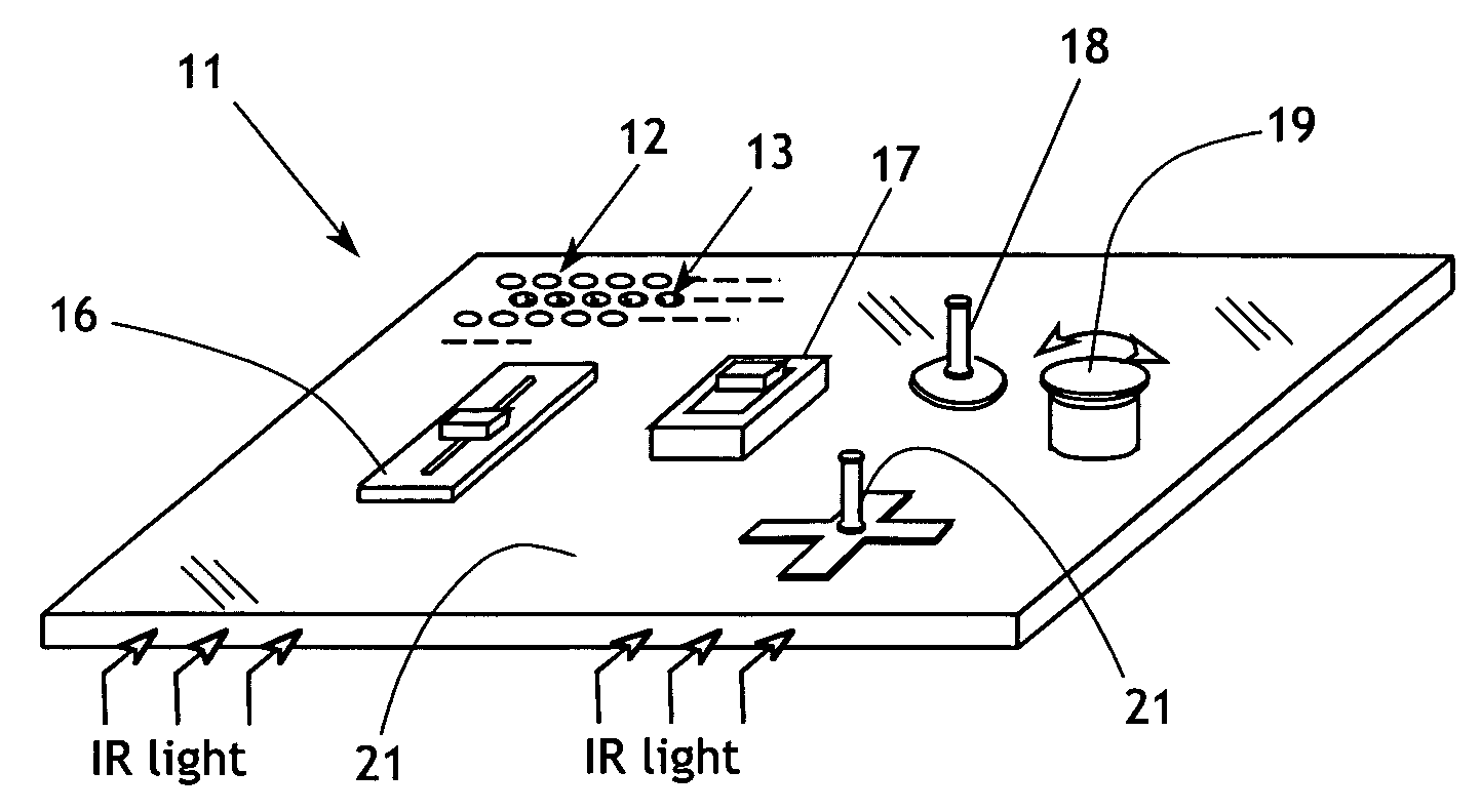
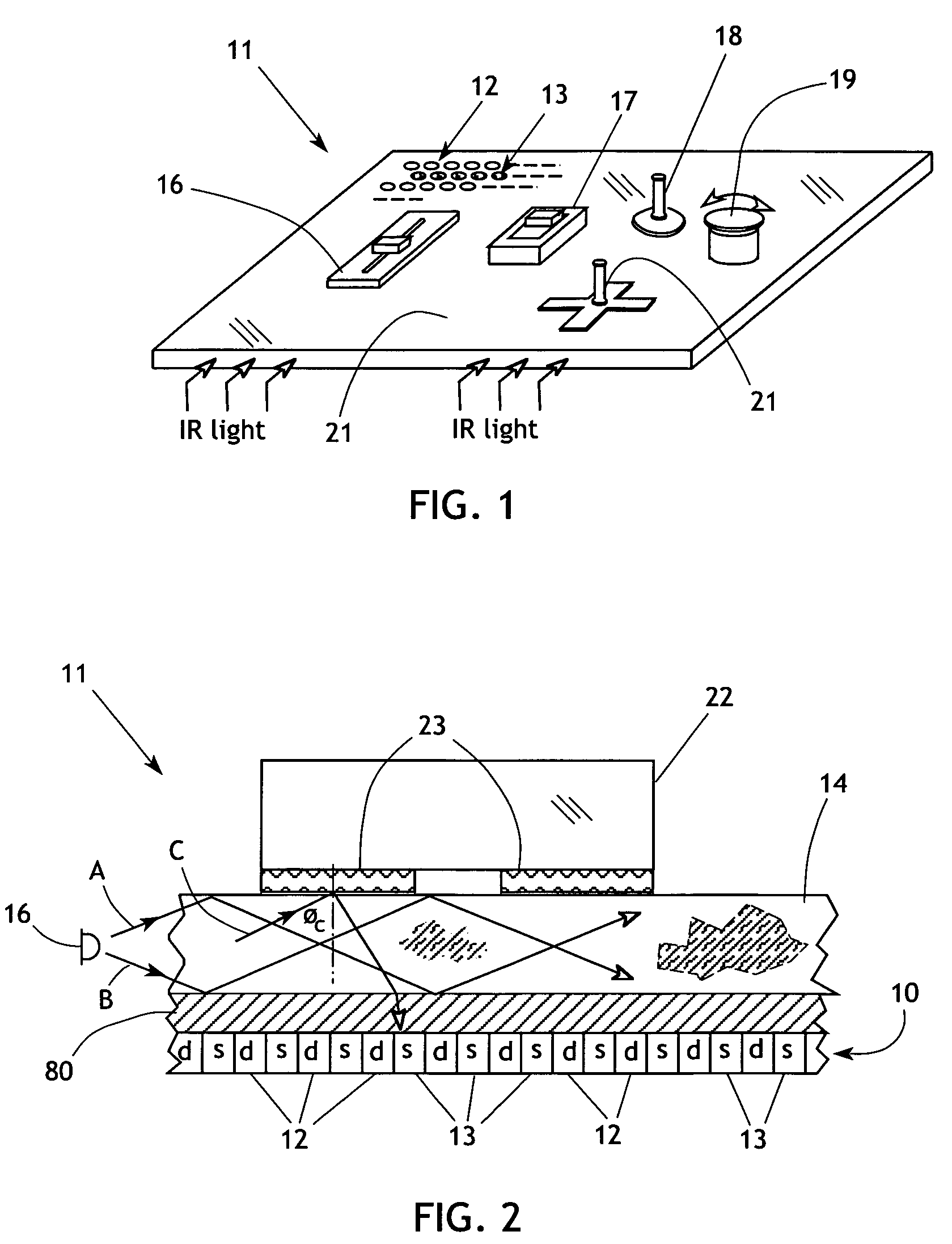
[0030]The present invention comprises apparatus used in conjunction with a combined screen 11 used for display and sensing of movement caused by finger touch or a stylus positioned on an acrylic layer overtop of the sensing screen. As shown in FIGS. 1 and 2, the screen has a combination of a plurality of pixels (d) 12 dedicated for display of the usual RGB color outputs, as well as a plurality of embedded sensors (s) 13 intermingled with the pixels 12 in a common stratum or layer 10. Although the drawing shows the two components 12 and 13 in alternating rows, it may be appreciated that there are many distribution pattern or array that may be used to accomplish the functions described below. The pixels 12 may be addressed in any manner known in the prior art, such as raster scanning or line scanning, to generate modulated light in their respective colors and combine to form an image display. Likewise, the sensors may be addressed in any manner known in the art to access the individua...


PUM


Abstract

A method and apparatus used in conjunction with a combined display/sensing screen (DSS) includes a transparent outer layer overtop of the sensing screen. A plurality of IR emitters inject IR light edgewise into the outer layer, where it undergoes total internal reflection. Touch input devices have reflective pads on them with a high index of refraction which alters the critical angle in the contact area so that some of the IR is refracted out of the surface and then reflected back through the outer layer to the DSS, where the IR sensor array will detect the position of the reflected light and register a signal. The sensor array signals may be combined into a sensor image to detect touch input devices and movement thereof.

Description

CROSS-REFERENCE TO RELATED APPLICATIONS[0001]This utility application claims the priority benefit of the filing date of related Prov. Appl. 60 / 901,478, filed Feb. 13, 2007.FEDERALLY SPONSORED RESEARCH[0002]Not applicable.SEQUENCE LISTING, ETC ON CD[0003]Not applicable.BACKGROUND OF THE INVENTION[0004]1. Field of the Invention[0005]This invention relates to touch screens that are associated with electronic displays and, more particularly, to arrangements for sensing touch inputs using IR light.[0006]2. Description of Related Art[0007]Display screen technology has advanced to the point where sensor elements may be dispersed or distributed among the picture elements that comprise an electronic display. One such system is described in Publication US2006 / 0007222, dated Jan. 12, 2006 in which the pixel elements are interspersed with photosensor elements, whereby the display may output an image while also receiving an image through the photosensor elements. Likewise, Publication US2006 / 009...

Claims


Application Information

Patent Timeline
IPC IPC(8): G06F3/041
CPCG06F2203/04109G06F3/0421
Inventor JAEGER, DENNYLOHBIHLER, ANDREW
Owner NBOR CORP
Why Eureka
Try Eureka