Display Screen Turning Apparatus

a technology of turning apparatus and display screen, which is applied in the direction of electric apparatus casings/cabinets/drawers, instruments, machine supports, etc., can solve the problems of disadvantageous unnecessary disadvantageous increase of monitor positioner (display screen turning apparatus), disadvantageous increase of vertical movement portion, etc., to inhibit unnecessary jolting of display screen, the effect of reducing the size of the apparatus

Inactive Publication Date: 2008-08-14
FUNAI ELECTRIC CO LTD
View PDF4 Cites 17 Cited by
  • Summary
  • Abstract
  • Description
  • Claims
  • Application Information

AI Technical Summary

Benefits of technology

[0015]The present invention has been proposed in order to solve the aforementioned problems, and an object of the present invention is to provide

Problems solved by technology

In the conventional monitor positioner proposed in the aforementioned Japanese Utility Model Registration No. 3079007, however, the planar portions of the through-shaft of the pivot come into contact with the inner side surface of the figure-eight limiting hole thereby regulating rotation of the monitor when the monitor is rotated frontward or rearward by the prescribed angle, while rotation of the through-shaft is not regulated when the monitor is vertically arranged with respect to the main seat.
Therefore, the monitor (display screen) disadvantageously unnecessarily jolts due to insufficient clamping force (tightening torque of the nut) for the through-shaft with respect to the fixed seat or the own weight of the monitor.
If the radius of rotation of the pivot is merely increased, however, the size (height, for example) of the monitor positioner (display screen turning apparatus) may be disadvantageously increased.
Therefore, the vide camera disadvantageously unnecessarily jolts with the vertical movi

Method used


Image

  • Display Screen Turning Apparatus
  • Display Screen Turning Apparatus
  • Display Screen Turning Apparatus

Examples


Embodiment Construction

[0052]An embodiment of the present invention is now described with reference to the drawings.

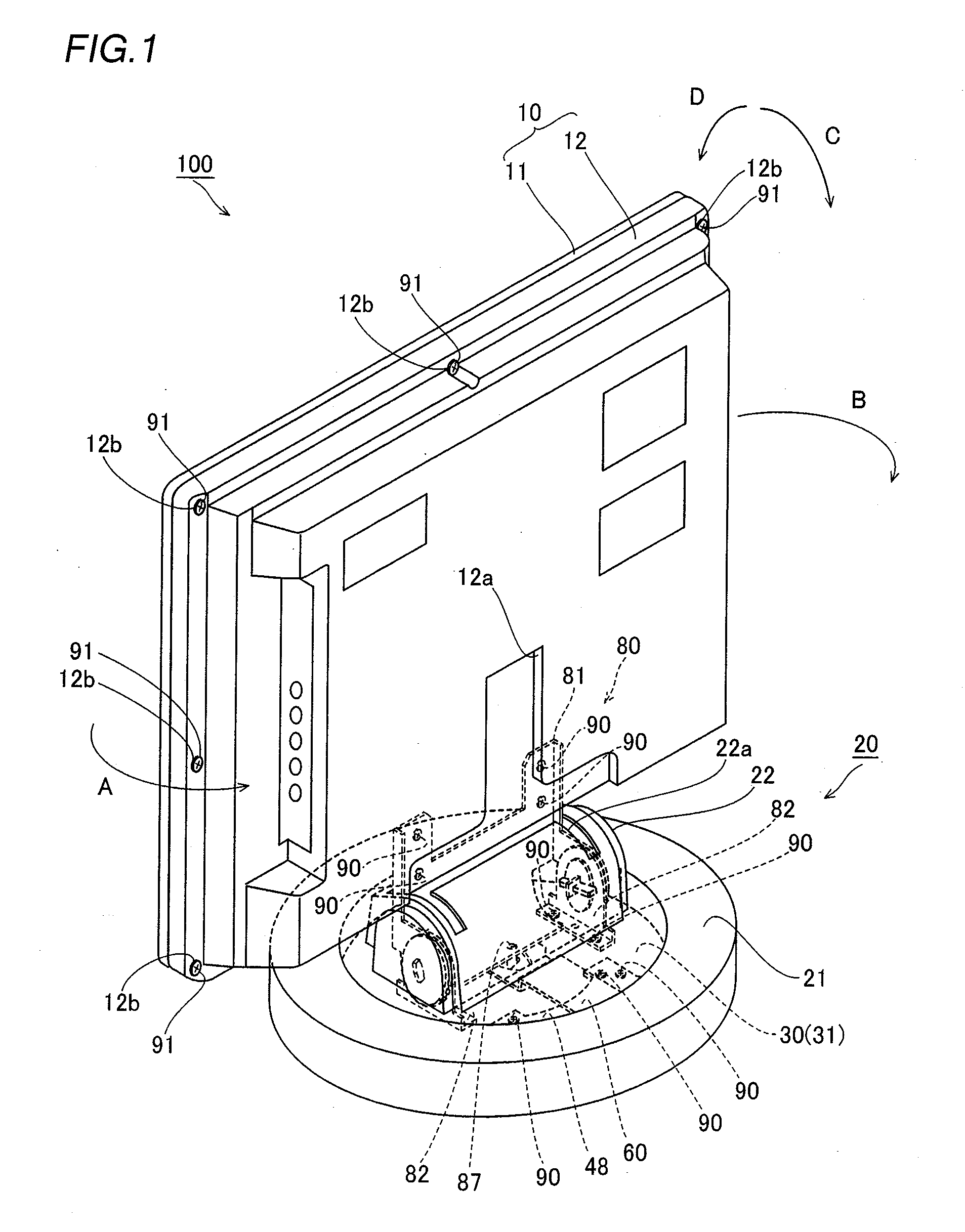
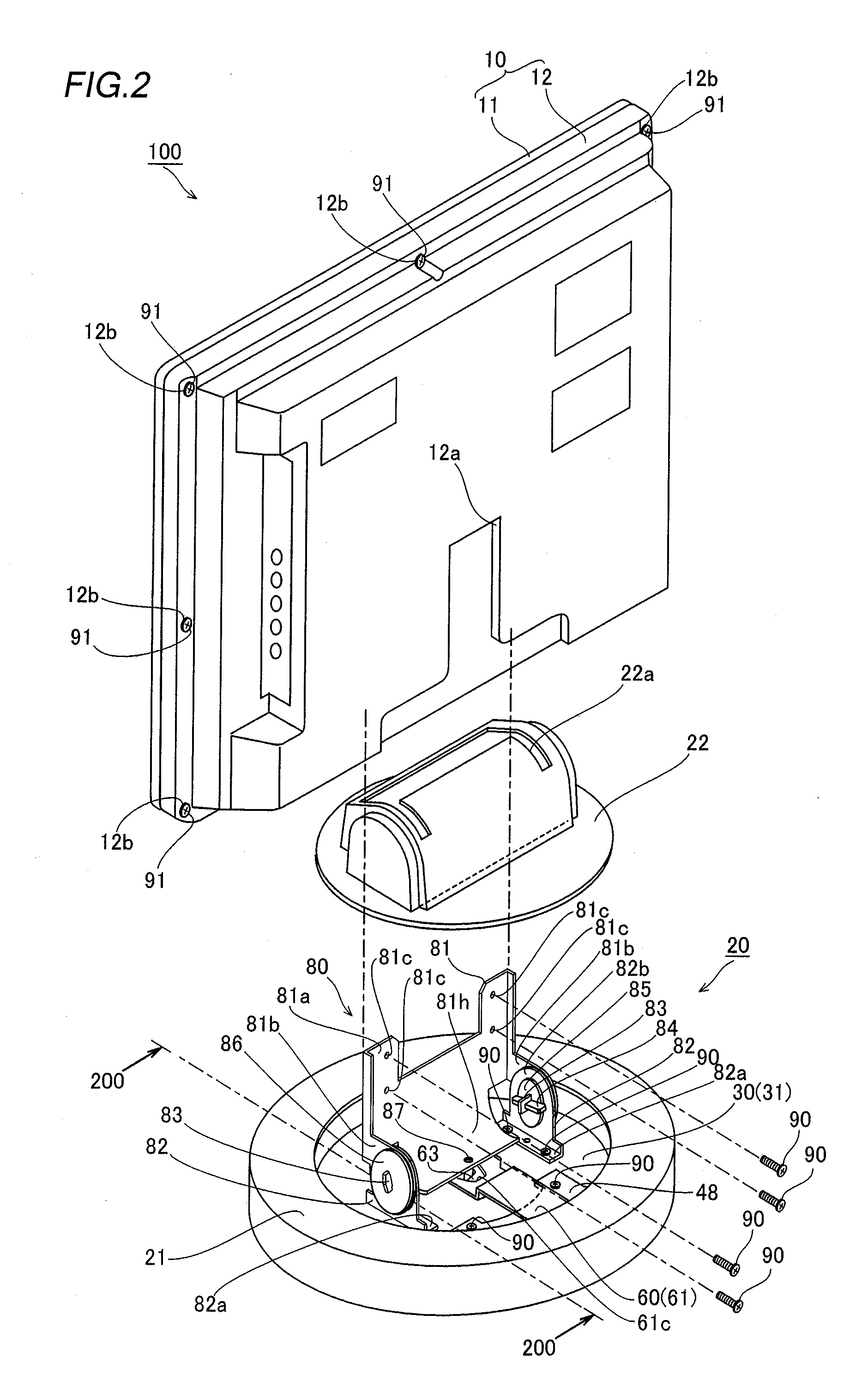
[0053]First, the structures of a display screen turning apparatus 20 according to the embodiment of the present invention and a liquid crystal television 100 provided with the display screen turning apparatus 20 are described with reference to FIGS. 1 to 14. According to this embodiment, the present invention is applied to the display screen turning apparatus 20 constituting the liquid crystal television 100 employed as an exemplary display.

[0054]The display screen turning apparatus 20 according to the embodiment of the present invention is so provided as to turn a display body 10 of the liquid crystal television 100 supported by a display screen support mechanism 80 in a horizontal direction (along arrow A or B) in a horizontal plane within a prescribed angular range (±30° in this embodiment) and to incline the display body 10 in an anteroposterior direction (along arrow C or D) with respec...


PUM


Abstract

A display screen turning apparatus capable of suppressing size increase of the apparatus and inhibiting a display screen from unnecessary jolting is obtained. This display screen turning apparatus includes a plate-shaped support shaft, a display screen support member, including a sectorial first hole receiving the plate-shaped support shaft, provided on the side of a display screen and rotatable around a first end, serving as the rotation center, of the plate-shaped support shaft and a base support member, including a sectorial second hole receiving the plate-shaped support shaft, provided on the side of a base, while a first root portion of the sectorial first hole closer to the center of a circle is arranged on the upper side of the first hole, a second root portion of the sectorial second hole closer to the center of a circle is arranged on the lower side of the second hole, and a first side surface of the plate-shaped support shaft inserted into the sectorial first hole is inclined by a prescribed angle with respect to a vertical direction to come into contact with a first inner side edge of the sectorial second hole of the base support member when the display screen is vertically arranged with respect to a horizontal plane along with the display screen support member.

Description

BACKGROUND OF THE INVENTION[0001]1. Field of the Invention[0002]The present invention relates to a display screen turning apparatus, and more particularly, it relates to a display screen turning apparatus comprising a display screen support member provided on the side of a display screen and a base support member provided on the side of a base.[0003]2. Description of the Background Art[0004]A display screen turning apparatus or the like for vertically or horizontally turning a display screen by a prescribed angle is known in general, as disclosed in each of Japanese Utility Model Registration Nos. 3079007 and 3092391, Japanese Patent Laying-Open No. 2001-146874, National Patent Publication Gazette No. 2004-522918 and Japanese Patent Laying-Open No. 2006-64786, for example.[0005]The aforementioned Japanese Utility Model Registration No. 3079007 discloses a monitor positioner (display screen turning apparatus) comprising a fixed seat fixed onto a main seat (base) and provided with a f...

Claims


Application Information

Patent Timeline
IPC IPC(8): H05K7/14
CPCF16M11/08F16M11/10Y10T16/2771F16M11/2014F16M2200/08F16M11/18
Inventor SAWAI, KUNIO
Owner FUNAI ELECTRIC CO LTD
Why Eureka
Try Eureka