
Multiple pass write sequence for non-volatile storage

Active Publication Date: 2008-08-21
SANDISK TECH LLC
View PDF46 Cites 42 Cited by
  • Summary
  • Abstract
  • Description
  • Claims
  • Application Information

AI Technical Summary

Benefits of technology

[0015]A multi-pass pass programming process is disclosed that improves programming speed and maintains reasonably tight threshold voltage distributions.

Problems solved by technology

However, the time needed for programming also increases.

Method used


Image

  • Multiple pass write sequence for non-volatile storage
  • Multiple pass write sequence for non-volatile storage
  • Multiple pass write sequence for non-volatile storage

Examples


Embodiment Construction

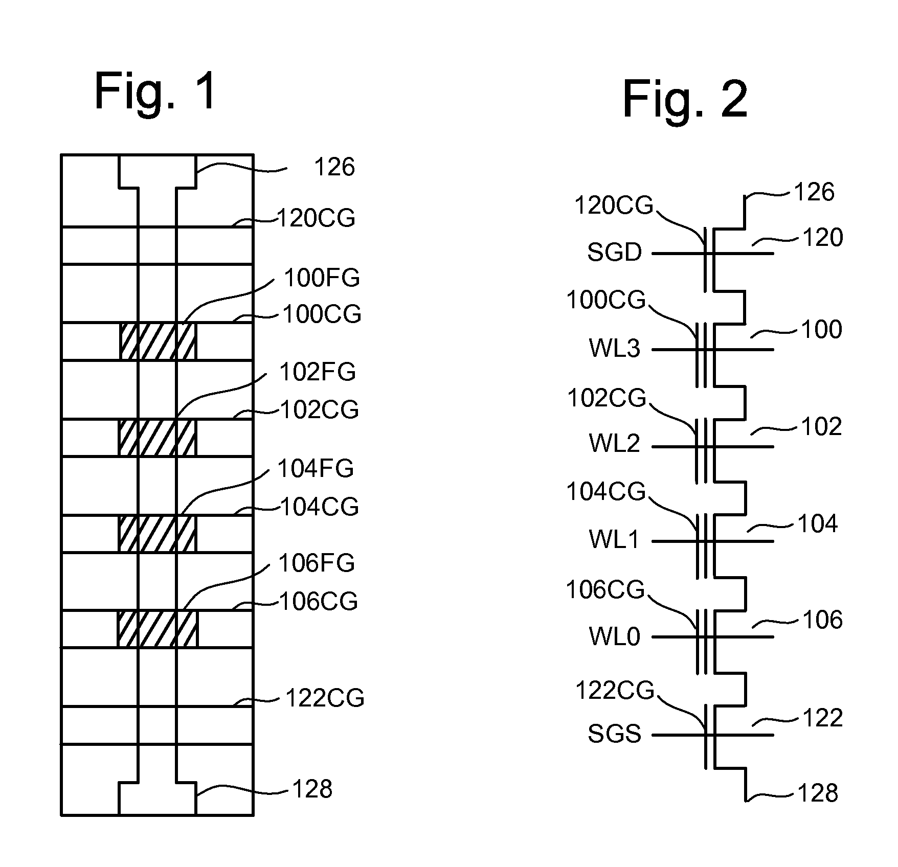
[0040]One example of a flash memory system uses the NAND structure, which includes arranging multiple transistors in series, sandwiched between two select gates. The transistors in series and the select gates are referred to as a NAND string. FIG. 1 is a top view showing one NAND string. FIG. 2 is an equivalent circuit thereof. The NAND string depicted in FIGS. 1 and 2 includes four transistors 100, 102, 104 and 106 in series and sandwiched between a first (or drain side) select gate 120 and a second (or source side) select gate 122. Select gate 120 connects the NAND string to a bit line via bit line contact 126. Select gate 122 connects the NAND string to source line 128. Select gate 120 is controlled by applying the appropriate voltages to select line SGD. Select gate 122 is controlled by applying the appropriate voltages to select line SGS. Each of the transistors 100, 102, 104 and 106 has a control gate and a floating gate. For example, transistor 100 has control gate 100CG and ...


PUM


Abstract

A set of non-volatile storage elements are erased to an erased threshold voltage distribution. A multi-pass programming process is performed that programs the set of non-volatile storage elements from the erased threshold voltage distribution to a set valid data threshold voltage distributions. Each programming pass has one or more starting threshold voltage distributions and programs non-volatile storage elements to at least two ending threshold voltage distributions.

Description

[0001]This application claims the benefit of provisional application No. 60 / 890,832, “Diagonal Sequence Write,” by Nima Mokhlesi, filed on Feb. 20, 2007, incorporated herein by reference in its entirety.CROSS-REFERENCE TO RELATED APPLICATIONS[0002]The following applications are cross-referenced and incorporated by reference herein in their entirety: U.S. patent application Ser. No. ______ [Attorney Docket No. SAND-01237US2], titled “Non-Volatile Storage Apparatus With Multiple Pass Write Sequence,” Inventor Nima Mokhlesi, filed the same day as the present application; U.S. patent application Ser. No. ______[Attorney Docket No. SAND-01239US0], titled “Variable Initial Program Voltage Magnitude For Non-Volatile Storage,” Inventor Nima Mokhlesi, filed the same day as the present application; U.S. patent application Ser. No. ______ [Attorney Docket No. SAND-01239US1], titled “Non-Volatile Storage Apparatus With Variable Initial Program Voltage Magnitude,” Inventor Nima Mokhlesi, filed t...

Claims


Application Information

Patent Timeline
IPC IPC(8): G11C11/34
CPCG11C5/147G11C8/10G11C11/5628G11C2211/5621G11C16/3418G11C16/3454G11C16/3459G11C16/0483
Inventor MOKHLESI, NIMA
Owner SANDISK TECH LLC
Learn More