Multiuser detector for variable spreading factors

a multi-user detector and variable spreading factor technology, applied in multiplex communication, radio transmission, electrical equipment, etc., can solve the problems of complex inversion of objective matrix o, computationally intensive, and difficult economic implementation of optimal multi-user detectors, so as to reduce computational complexity and minimize numeric operations

Inactive Publication Date: 2008-08-21
INTERDIGITAL TECH CORP
View PDF16 Cites 17 Cited by
  • Summary
  • Abstract
  • Description
  • Claims
  • Application Information

AI Technical Summary

Benefits of technology

[0044]The present invention relates to a multiuser detector method and receiver that detects and decodes synchronous or asynchronous CDMA subchannels having different spreading factors with reduced computational complexity. The multiuser receiver of the present invention is preferably compatible with ZF-BLE, MMSE, decorrelating detectors and the like using Cholesky decomposition to minimize numeric operations. The receiver and method arranges the columns of system transmission response matrices representing the response characteristics of individual users into a well-banded total system transmission response matrix which represents a plurality of matched-filter responses for a given block of received data. The invention when used in conjunction with Cholesky decomposition reduces the number of required mathematic operations prior to parallel matched filtering.

Problems solved by technology

Optimal multiuser detectors are computationally intensive devices performing numerous complex mathematic operations and are therefore difficult to implement economically.
The inversion of the objective matrix O is a complex, computationally intensive process.
Therefore, Cholesky decomposition cannot be used effectively to reduce the operational complexity when inverting matrix O. However, the prior art discloses that when all users transmit with equal spreading factors, a re-arrangement of the total system transmission response matrix A can be performed prior to calculating an objective matrix O, turning matrix O into a banded matrix.
However, the prior art has not addressed a re-arrangement method for when different spreading factors are in use between active users.

Method used


Image

  • Multiuser detector for variable spreading factors
  • Multiuser detector for variable spreading factors
  • Multiuser detector for variable spreading factors

Examples


Embodiment Construction

)

[0057]The embodiments will be described with reference to the drawing figures where like numerals represent like elements throughout.

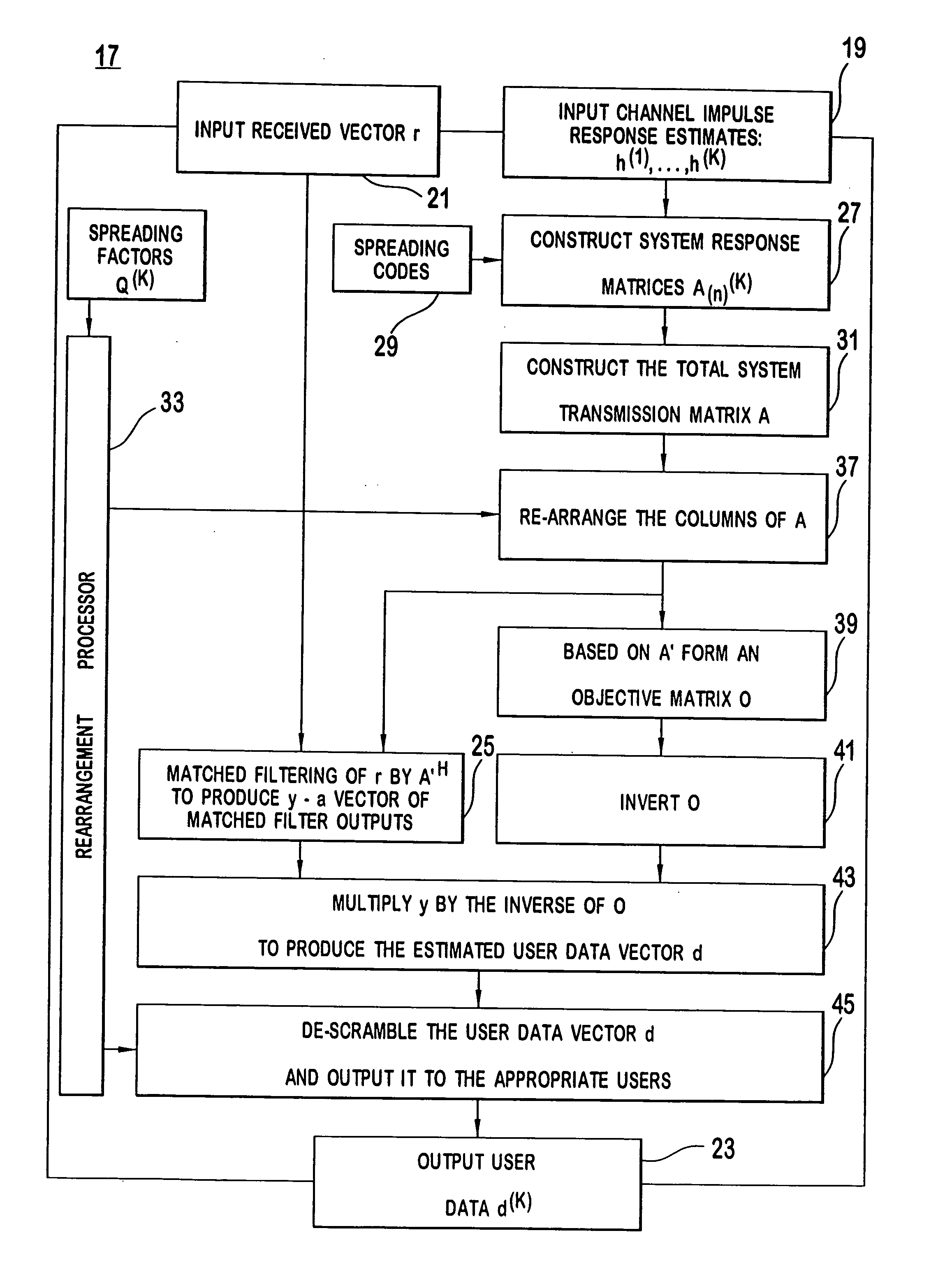
[0058]Shown in FIG. 7 is a multiuser detector 17 of the present invention for detecting, after reception, a plurality of users transmitting over a common CDMA channel. The multiuser detector 17 comprises a plurality of processors having collateral memory which perform various vector and matrix operations. Alternate embodiments of the invention include fixed gate arrays and DSPs performing the functions of the various processors. The detector 17 also comprises a first input 19 for inputting individual k subchannel impulse response estimates modeled as vectors h(k) to correct intersymbol interference or ISI caused by a subchannel's own symbols and multiple access interference or MAI caused by symbols from other user's subchannels for all received data signals, a second input 21 for inputting data from all users k transmitted in a discreet block of time ...


PUM


Abstract

A multiuser detector method and receiver that detects and decodes synchronous or asynchronous CDMA subchannels having different spreading factors with reduced computational complexity. The multiuser receiver is compatible with ZF-BLE, MMSE, decorrelating detectors and the like using Cholesky decomposition to minimize numeric operations. The receiver and method arranges the columns of system transmission response matrices representing the response characteristics of individual users into a total system transmission response matrix which represents a plurality of matched-filter responses for a given block of received data. The invention when used in conjunction with Cholesky decomposition reduces the number of required mathematic operations prior to parallel matched filtering.

Description

[0001]This application is a continuation of U.S. patent application Ser. No. 10 / 100,997, filed Mar. 19, 2002, which is a continuation of international application No. PCT / US00 / 02621, filed Feb. 2, 2000, which claims priority to U.S. Provisional Patent Application No. 60 / 154,985, filed Sep. 21, 1999, all of which are incorporated by reference.BACKGROUND[0002]1. Field of the Invention[0003]The present invention relates generally to multiple access digital communication systems. More specifically, the invention relates to a multiuser detector system and method for the simultaneous reception of data from multiple users having different spreading factors.[0004]2. Description of the Related Art[0005]A multiple-access communication system allows a plurality of users to access the same communication medium to transmit or receive information. The media may comprise, for example, a network cable in a local area network or lan, a copper wire in the classic telephone system, or an air interface...

Claims


Application Information

Patent Timeline
Patent Type & Authority Applications(United States)
IPC IPC(8): H04B7/216H04B1/707H04J13/02
CPCH04B1/7093H04B1/7105H04B2201/70705H04B2201/70703H04B1/71052
Inventor REZNIK, ALEXANDERLUBECKI, TIMOTHY J.ZEIRA, ARIELA
Owner INTERDIGITAL TECH CORP
Why Eureka
Try Eureka