
Image forming apparatus having fixing device

a technology of fixing device and image forming apparatus, which is applied in the direction of electrographic process apparatus, instruments, optics, etc., can solve the problems of high temperature of fixing device, loss of belt durability, and risk of cleaning by an operator, so as to increase the manufacturing cost of image forming apparatus, the effect of safe and simple cleaning of fixing devi

Inactive Publication Date: 2008-08-21
KONICA MINOLTA BUSINESS TECH INC
View PDF14 Cites 21 Cited by
  • Summary
  • Abstract
  • Description
  • Claims
  • Application Information

AI Technical Summary

Benefits of technology

"The present invention aims to provide an image forming apparatus that can safely and easily clean the fixing device without damaging it or increasing manufacturing costs. The apparatus includes an image forming section, a fixing device, a registration roller, and a controller. The controller controls the execution of a cleaning mode and the conveyance of the sheet. The controller removes toner adhered onto the fixing member by pressing and releasing the pressing member before the sheet passes through the nip portion of the fixing member. The technical effect of this invention is to provide a more efficient and cost-effective way to clean the fixing device in an image forming apparatus."

Problems solved by technology

However, the temperature of the fixing device is very high and there is a case that the cleaning by an operator is at risk.
However, in case that the cleaning mechanism has been provided in the fixing device, the fixing belt is worn out and deteriorated due to the cleaning by the cleaning mechanism, and there is a possibility that belt durability is lost.
Further, in case when the cleaning mechanism is provided in the image forming apparatus, the manufacturing process of the image forming apparatus becomes complicated and the cost of the image forming apparatus increases.
In this case, sheet jam due to the residual toner occurs.
In case when sheet jam occurs in the sheet feed of the cleaning mode, the toner dirt of the fixing device is not resolved and the sheet feed needs to be executed again, which makes the cleaning mode complicated.
Further, the efficiency of the sheet feed by the cleaning mode decreases.
However, every time when executing a cleaning mode, the dedicated cleaning sheet has to be set, which makes the cleaning of the fixing device complicated.

Method used


Image

  • Image forming apparatus having fixing device
  • Image forming apparatus having fixing device
  • Image forming apparatus having fixing device

Examples


Embodiment Construction

[Structure]

[0031]Image forming apparatuses, such as, a printer, which is capable of outputting color images, and a color multifunction peripheral including a copier and a facsimile machine, will be described as embodiments of the present invention.

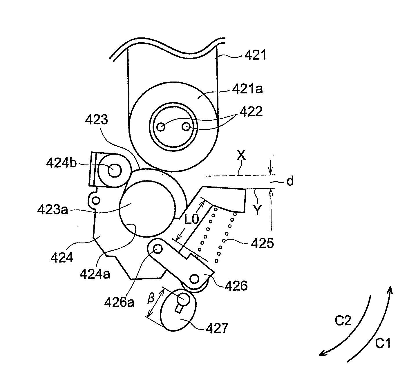
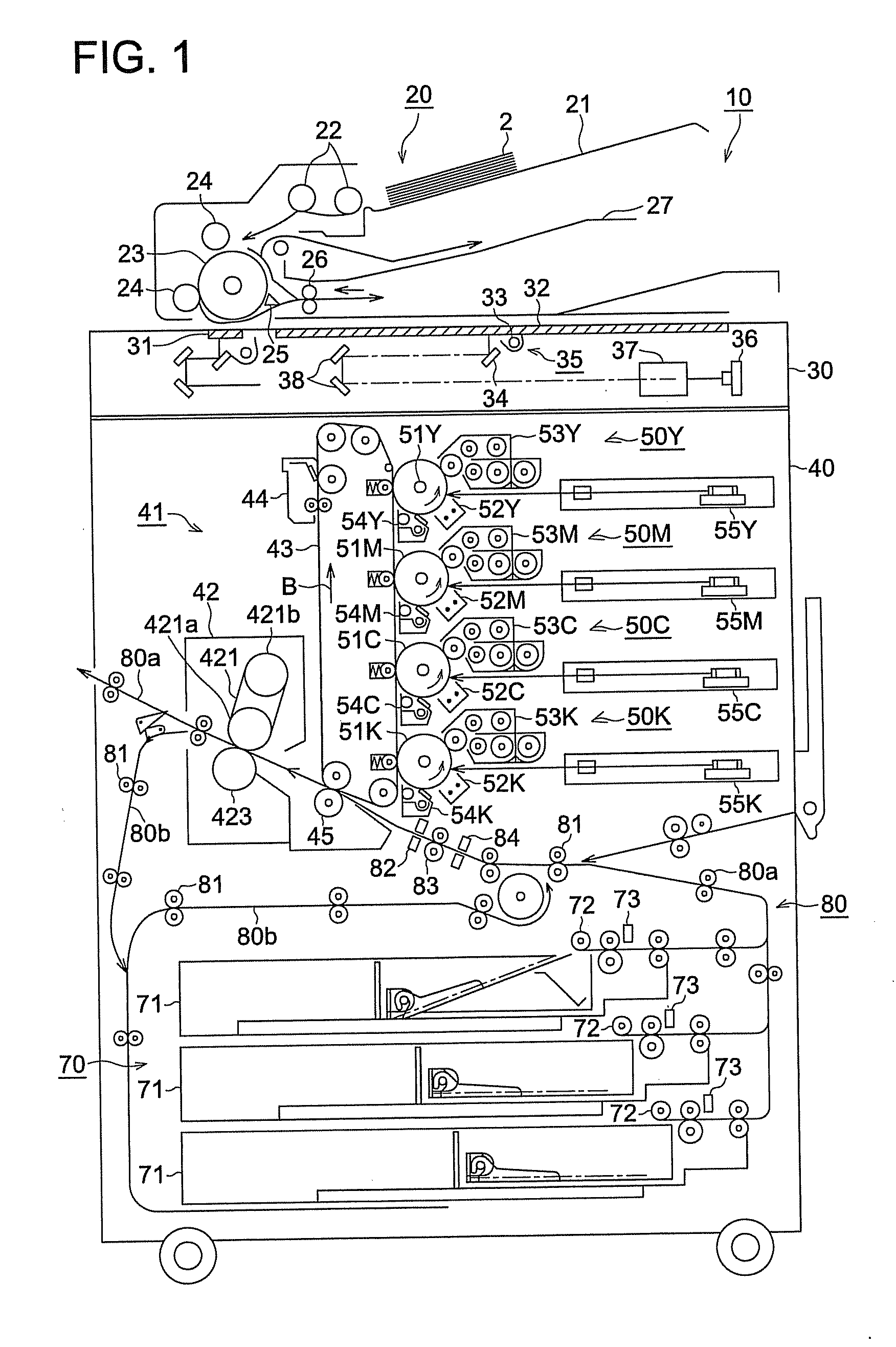
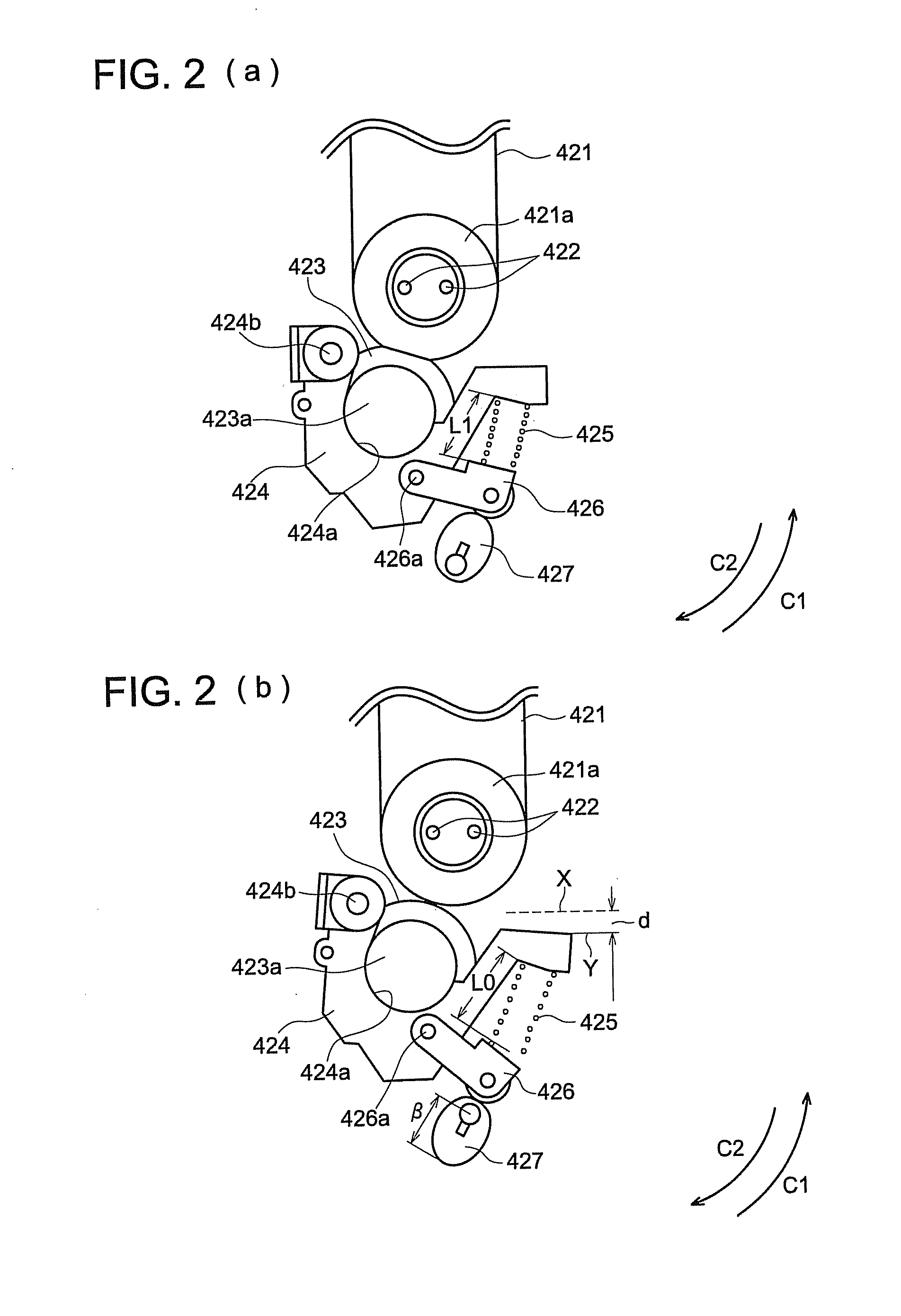
[0032]The structure of an image forming apparatus 10 will be described by referring to FIGS. 1-3. FIG. 1 illustrates a schematic structure of the image forming apparatus 10 of an embodiment of the present invention. FIGS. 2(a)-2(b) illustrate schematic drawings of a fixing device 42 of the image forming apparatus 10 pertaining to the embodiment of the present invention. FIG. 2(a) illustrates a pressure-contact state and FIG. 2(b) illustrates a pressure-contact release state. FIG. 3 illustrates a block diagram of a schematic structure of control of the image forming apparatus 10 pertaining to the embodiment of the present invention.

[Image Forming Apparatus]

[0033]As illustrated in FIG. 1, the image forming apparatus 10 includes an automatic ...


PUM


Abstract

An image forming apparatus which forms an image on a sheet, includes a controller which executes a cleaning mode in which the controller conveys the sheet from a sheet feed tray to a fixing device without forming a toner image on the sheet, removes toner that has been adhered to a fixing member to clean. In case the cleaning mode is executed, the controller controls a releasing section to release pressure contact of a pressing member before a leading edge of the sheet in a sheet conveyance direction reaches a nip portion between the fixing member and the pressing member, and to bring the pressing member into pressure contact with the fixing member after the leading edge of the sheet has passed through the nip portion.

Description

[0001]This application is based on Japanese Patent Application Nos. 2007-040044 filed on Feb. 20, 2007, and 2007-281267 filed on Oct. 30, 2007, which are incorporated hereinto by reference.BACKGROUND OF THE INVENTION[0002]The present invention relates to a technology for conducting cleaning of a fixing device for fixing a toner image onto the sheet in the image forming apparatus, such as a printer, a copier and a facsimile machine of an electro-photographic system.[0003]An image forming apparatus of an electro-photographic system transfers a toner image onto a sheet and the toner image is fixed onto the sheet by heating with the fixing device.[0004]On this image forming process, there is a case that a sheet jam is generated as a sheet gets stuck in the fixing device. FIG. 9 illustrates the situation of occurrence of sheet jam in the fixing device. FIG. 9 illustrates a schematic cross sectional view showing the sheet P, which generates the jam in the printer section in the image form...

Claims


Application Information

Patent Timeline
Patent Type & Authority Applications(United States)
IPC IPC(8): G03G15/20
CPCG03G15/2025
Inventor SUZUKI, CHIKATSUTAKI, KENJIAKIMOTO, FUSAKO
Owner KONICA MINOLTA BUSINESS TECH INC
Learn More