Photography device and display control method

Active Publication Date: 2014-01-02
FUJIFILM CORP
View PDF0 Cites 13 Cited by
  • Summary
  • Abstract
  • Description
  • Claims
  • Application Information

AI Technical Summary

Benefits of technology

[0022]Because the display control method of the present invention also operates similarly to the photography device of the present invention, the effects of changes in the photographing conditions can be provided to the user in real time without deterior

Problems solved by technology

On the other hand, at an OVF, the setting effects of the photographing conditions, such as the exposure settings, the white balance (WB), depth of field, and the like are not displayed such as at an EVF, and therefore, the user cannot know of the setting effects.
Thus, when photographing is carried out by using an OVF and at the usual automatic settings as are, depending on the conditions, it is possible for failures to occur such as out of focus occurring, or night views being too light, or the WB not being suitable, or the like.
This switching of the display of the finder is inconvenient for the user, and it is difficult to say that the user can grasp the situation in real time.
However, when the photographing settings are to be changed drastically such a

Method used


Image

  • Photography device and display control method
  • Photography device and display control method
  • Photography device and display control method

Examples


Embodiment Construction

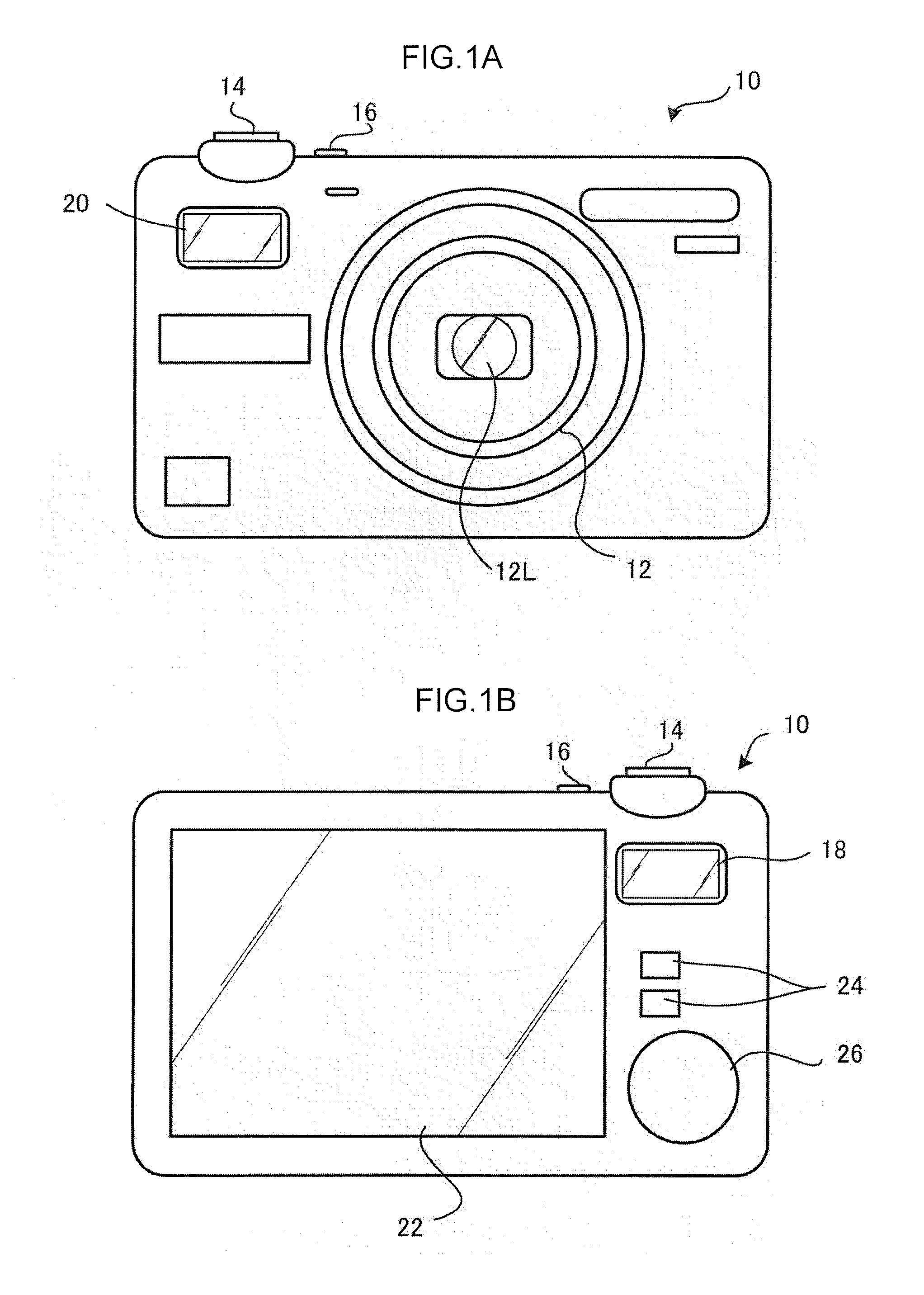
[0051]As shown in FIG. 1A, a lens barrel 12 having a lens 12L for image-forming an image of a photographic subject is provided at the front surface of a digital camera 10 that serves as a photography device. A release button (a so-called shutter) 14, that is push-operated by the user at the time of executing image pickup (photography), and a power switch 16 are provided at the top surface.

[0052]Note that the release button 14 relating to the present embodiment is structured so as to be able to detect push-operations of two stages that are a state in which the release button 14 is pushed-down to an intermediate position (hereinafter called “half-depressed state” or “S1 on state”), and a state in which the release button 14 is pushed-down to a final pushed-down position that is past the intermediate position (hereinafter called “fully depressed state” or “S2 on state”).

[0053]The digital camera 10 is structured such that, due to the release button 14 being set in the aforementioned hal...


PUM


Abstract

There is provided a photography device including: a display control section; a guiding section; and a guiding control section that, in a state in which the optical image has been guided to the eyepiece portion and the electronic image and the composite image have not been guided to the eyepiece portion, if the photographing conditions are changed, carries out first control that controls the guiding section such that the composite image is guided to the eyepiece portion, and, if a predetermined time elapses after the first control or a predetermined operation is carried out by a user after the first control, carries out second control that controls the guiding section such that the optical image is guided to the eyepiece portion and the electronic image and the composite image are not guided to the eyepiece portion.

Description

CROSS-REFERENCE TO RELATED APPLICATIONS[0001]This application is a continuation application of International Application No. PCT / JP2012 / 052782, filed Feb. 7, 2012, the disclosure of which is incorporated herein by reference in its entirety. Further, this application claims priority from Japanese Patent Application No. 2011-048041, filed Mar. 4, 2011, the disclosure of which is incorporated herein by reference in its entirety.BACKGROUND[0002]1. Technical Field[0003]The present invention relates to a photography device and a display control method that are equipped with an optical view finder (OVF), that displays an optical image that is inputted optically, and an electrical view finder (EVF) mode, that displays an electronic image that has been picked-up by the image pickup element, that are finders that specify and display at least an image pickup range.[0004]2. Related Art[0005]There has conventionally been proposed a hybrid view finder (HVF) that has an optical system that leads a...

Claims


Application Information

Patent Timeline
IPC IPC(8): H04N5/232
CPCH04N5/23293H04N2201/0084G03B13/06G03B17/20H04N23/673H04N23/61H04N23/611H04N23/635
Inventor SAKURABU, HITOSHI
Owner FUJIFILM CORP
Why Eureka
Try Eureka