Power reception control device, power transmission control device, non-contact power transmission system, power reception device, power transmission device, and electronic instrument

a technology of power transmission control and power reception device, which is applied in the direction of pulse characteristics measurement, instruments, pulse techniques, etc., can solve the problems of product fire, product burn, and disadvantage of technology

Active Publication Date: 2008-08-21
SEIKO EPSON CORP +1
View PDF20 Cites 99 Cited by
  • Summary
  • Abstract
  • Description
  • Claims
  • Application Information

AI Technical Summary

Benefits of technology

[0011]According to one aspect of the invention, there is provided a power reception control device that is provided in a power reception device that is included in a non-contact power transmission system, the non-contact power transmission system transmitting power f...

Problems solved by technology

The user may be burned when the metallic foreign object reaches a high temperature.
Moreover, when the product is partially melted due to heat generated from the metallic foreign object, the product may catch fire.
Since instruments are designed to reduce the space in which a foreign object is inserted by minimizing the space between a power transmission device and a power reception device, the above-mentioned problem generally rarely occurs.
Howev...

Method used


Image

  • Power reception control device, power transmission control device, non-contact power transmission system, power reception device, power transmission device, and electronic instrument
  • Power reception control device, power transmission control device, non-contact power transmission system, power reception device, power transmission device, and electronic instrument
  • Power reception control device, power transmission control device, non-contact power transmission system, power reception device, power transmission device, and electronic instrument

Examples


first embodiment

[0124]Examples of an electronic instrument to which the invention is suitably applied and the principle of non-contact power transmission technology are described below.

[0125]Examples of electronic instrument and principle of non-contact power transmission

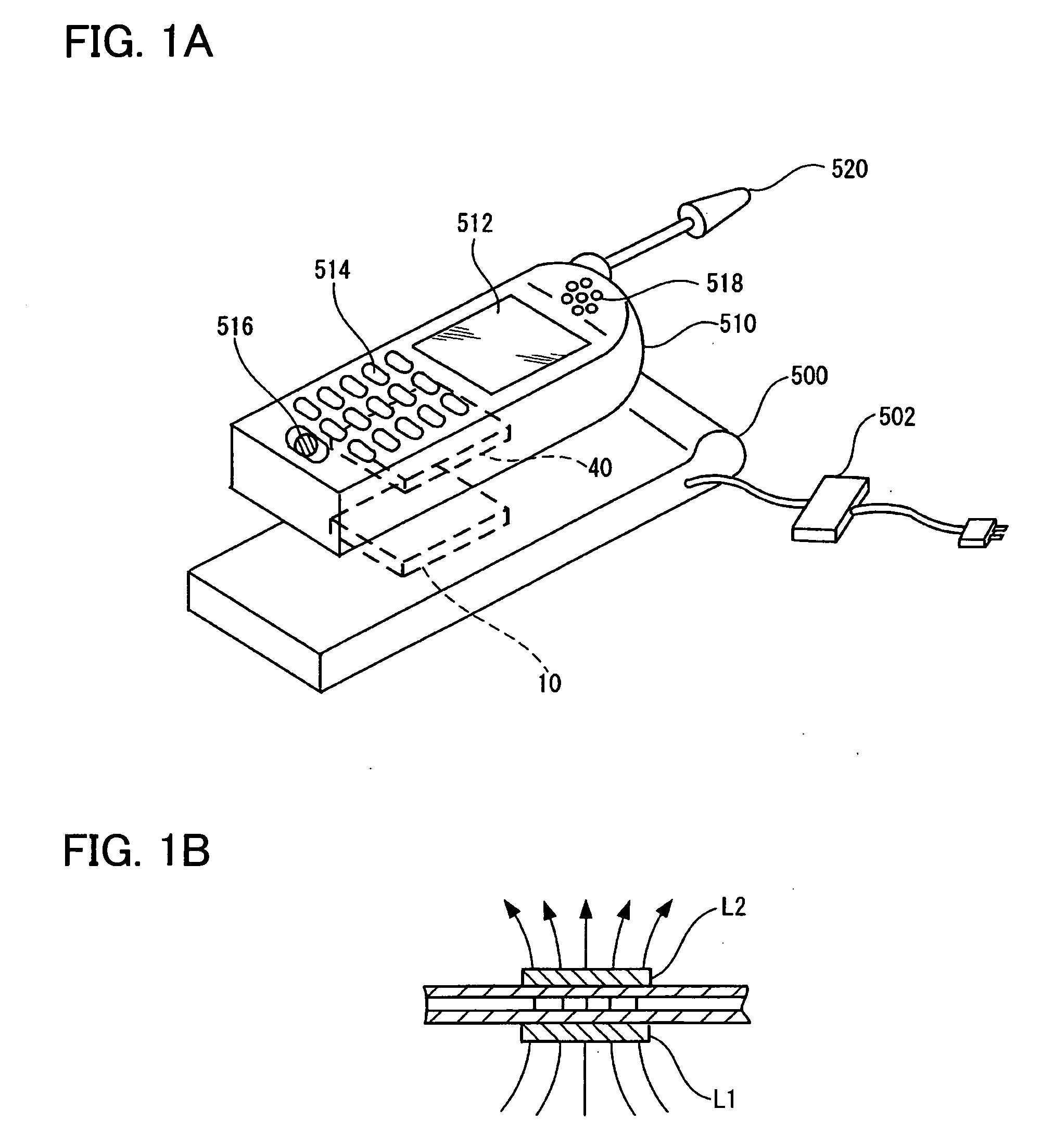
[0126]FIGS. 1A and 1B are views illustrative of non-contact power transmission technology. FIG. 1A is a view showing examples of an electronic instrument to which non-contact power transmission is applied. FIG. 1B is a view illustrative of the principle of non-contact power transmission using an induction transformer.

[0127]As shown in FIG. 1A, a charger 500 (cradle) (i.e., electronic instrument) includes a power transmission device 10. A portable telephone 510 (i.e., electronic instrument) includes a power reception device 40. The portable telephone 510 also includes a display section 512 such as an LCD, an operation section 514 which includes a button or the like, a microphone 516 (sound input section), a speaker 518 (sound output...

second embodiment

[0191]This embodiment illustrates a specific configuration and operation suitable for detecting insertion of a foreign object.

[0192]Specific example of foreign object insertion detection

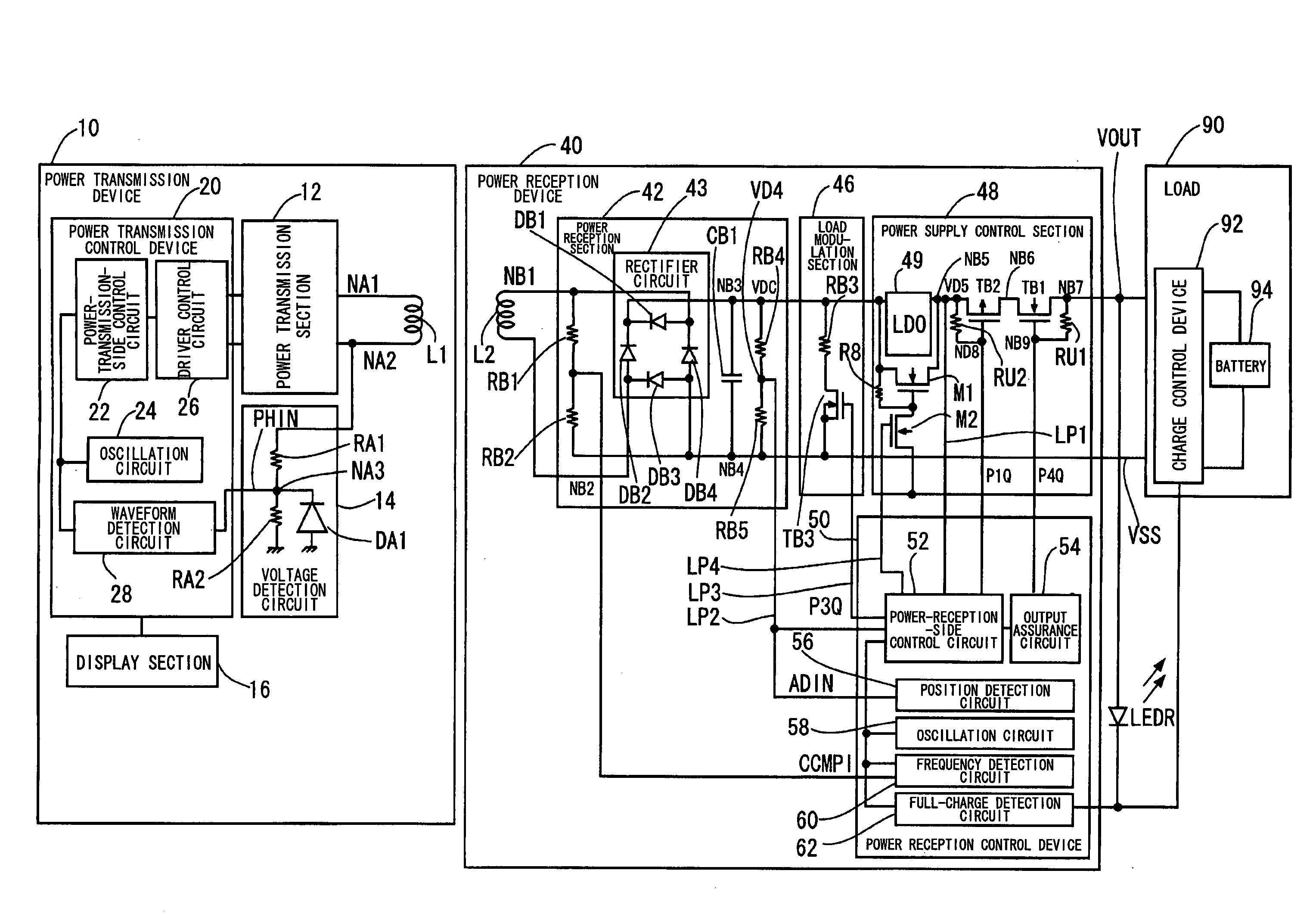
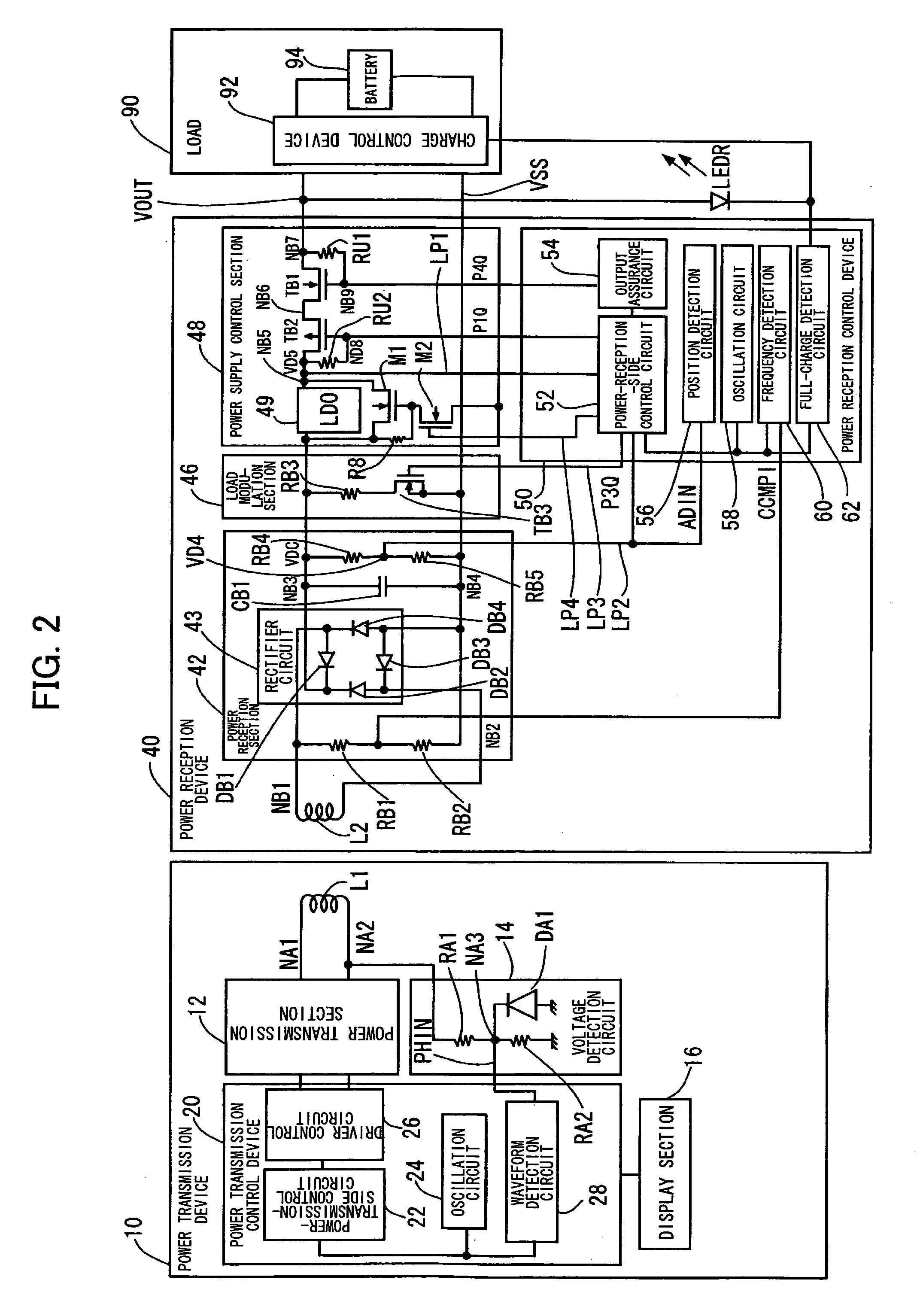
[0193]FIG. 7 is a circuit diagram showing the main configuration of the non-contact power transmission system shown in FIG. 2 relating to detection of insertion of a foreign object. In FIG. 7, the same sections as in FIG. 2 are indicated by the same reference symbols. In FIG. 7, a bold line indicates a portion that plays an important role in detecting insertion of a foreign object.

[0194]A notable circuit configuration of the power reception device 40 shown in FIG. 7 includes the load modulation transistor TB3 of the load modulation section 46 (see FIG. 2), the power supply control transistor TB2 of the power supply control section 48 (see FIG. 2), and the power-receiving-side control circuit 52 which ON / OFF-controls these transistors (TB2 and TB3). It is also important that the voltages at the input ...


PUM


Abstract

A power-receiving-side control circuit of a power reception device performs intermittent load modulation by causing an NMOS transistor to be turned ON/OFF during normal power transmission. A power-transmission-side control circuit included in a power transmission control device of a power transmission device monitors, an intermittent change in the load of the power reception device during normal power transmission. The power-transmission-side control circuit determines that a foreign object has been inserted between a primary coil and a secondary coil and stops power transmission when an intermittent change in load cannot be detected. The amount of power supplied to the load may be compulsorily reduced when the load state of the load is heavy.

Description

[0001]Japanese Patent Application No. 2007-36744 filed on Feb. 16, 2007, is hereby incorporated by reference in its entirety.BACKGROUND OF THE INVENTION[0002]The present invention relates to a power reception control device, a power transmission control device, a non-contact power transmission system, a power reception device, a power transmission device, an electronic instrument, and the like.[0003]In recent years, non-contact power transmission (contactless power transmission) which utilizes electromagnetic induction to enable power transmission without metal-to-metal contact has attracted attention. As application examples of non-contact power transmission, charging a portable telephone, a household appliance (e.g., telephone handset), and the like has been proposed.[0004]JP-A-2006-60909 discloses a non-contact power transmission device using a primary coil and a secondary coil, for example.[0005]When a non-contact power transmission system successively transmits power in a state...

Claims


Application Information

Patent Timeline
IPC IPC(8): H04B5/00H02J7/00H02M3/28
CPCH04B1/3883H04B5/0037H04B7/00H02J7/025H02J5/005H02J7/0044G01V3/10H02J50/90H02J50/12H02J50/60
Inventor ONISHI, KOTAYODA, KENTAROKAMIJO, TAKAHIROJIN, MIKIMOTOSOGABE, HARUHIKOKONDO, YOICHIROSUZUKI, KUNIHARUKATO, HIROSHISUZUKI, KATSUYAYAMAZAKI, MANABU
Owner SEIKO EPSON CORP
Why Eureka
Try Eureka