
Temporal Brow Lifting and Fixation Device

a technology of fixation device and brow, which is applied in the field of implantable tissue lifting and fixation device, can solve the problems of large scars, large bandaging, and patient susceptible to infections, and achieve the effect of increasing the section modulus of structural cross-sections and optimizing the strength-to-mass properties of the devi

Inactive Publication Date: 2008-08-21
HENDERSON JENIFER LEE
View PDF26 Cites 17 Cited by
  • Summary
  • Abstract
  • Description
  • Claims
  • Application Information

AI Technical Summary

Benefits of technology

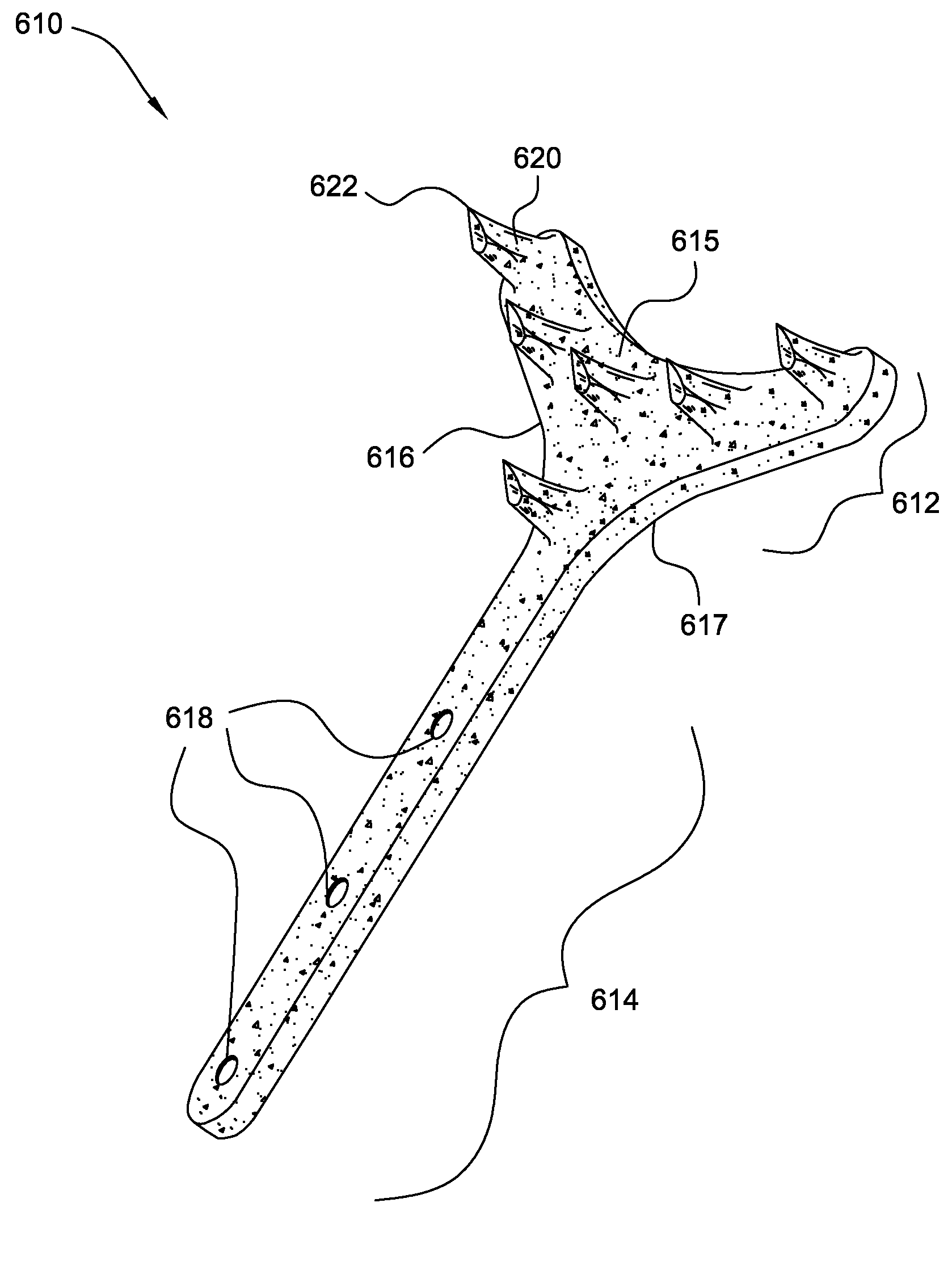
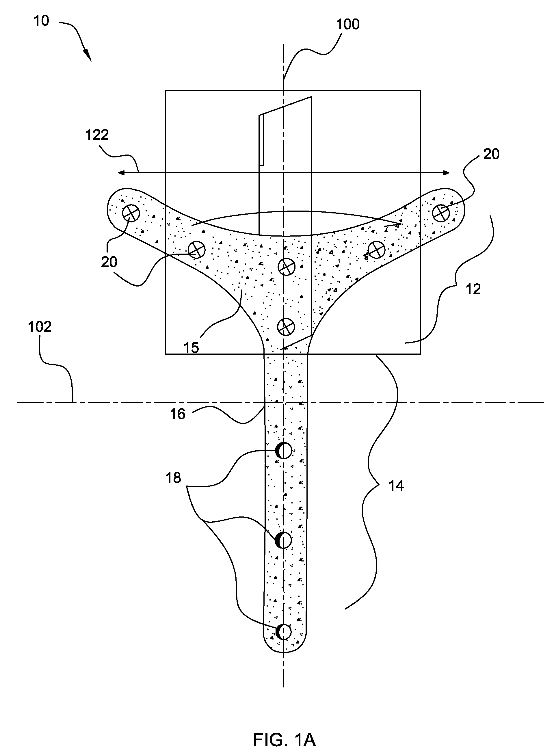
[0017]The supportive backing material might be produced from a more flexible polymer and the attachment points or tines of a stiffer material. The supportive backing, generally, is made of a bio-resorbable material that can have the structure of a mesh, net, or lattice. The extent of porosity or total surface area may be used to control the absorption rate of the device, and may also be used to optimize the strength-to-mass properties of the device, increasing the section modulus of structural cross-sections per unit mass. The backing structure may comprise partial folds, waves, or grooves to help hold tissue against both surfaces of the backing.

Problems solved by technology

These devices may leave the patient susceptible to infections, require a great deal of bandaging, and leave extensive scars.
However, the head of such screws or tacks and the gripping member of such appliances are bulky, making a prominent protrusion on the bone surface.
Suture fixation, generally, provides a single vector of pull which can result in an unnatural, tented appearance to the temporal brow.
Moreover, suture fixation can be cumbersome and may require several attempts by the surgeon to achieve bilateral symmetry.

Method used


Image

  • Temporal Brow Lifting and Fixation Device
  • Temporal Brow Lifting and Fixation Device
  • Temporal Brow Lifting and Fixation Device

Examples


Embodiment Construction

[0038]As used herein, the terms “temporal brow lifting device”, “brow lifting device”, or simply “fixation device” refer to an implantable tissue fixation device used in the brow lift surgery or similar surgical procedures. More specifically, these terms refer to device that maintains the elevation of the brow after surgical dissection is complete. The device will hold the tissue until healing or scar formation is complete. A non-exhaustive list of brow lifting surgical procedures includes direct brow lift, mid forehead lift, pretrichial lift, trichophyte lift, temporal lift, coronal lift, and endoscopic brow lift.

[0039]As used herein, the terms, “tines” or “prongs”, both, refer to the attachment points which are either sharp, i.e. able to separate tissue in a chosen use, or blunt, i.e. not able to separate tissue in that use. The attachment points may also be referred to as “barbs. Generally, the tines, prongs, or barbs penetrate into soft tissue and for a short distance. The attac...


PUM


Abstract

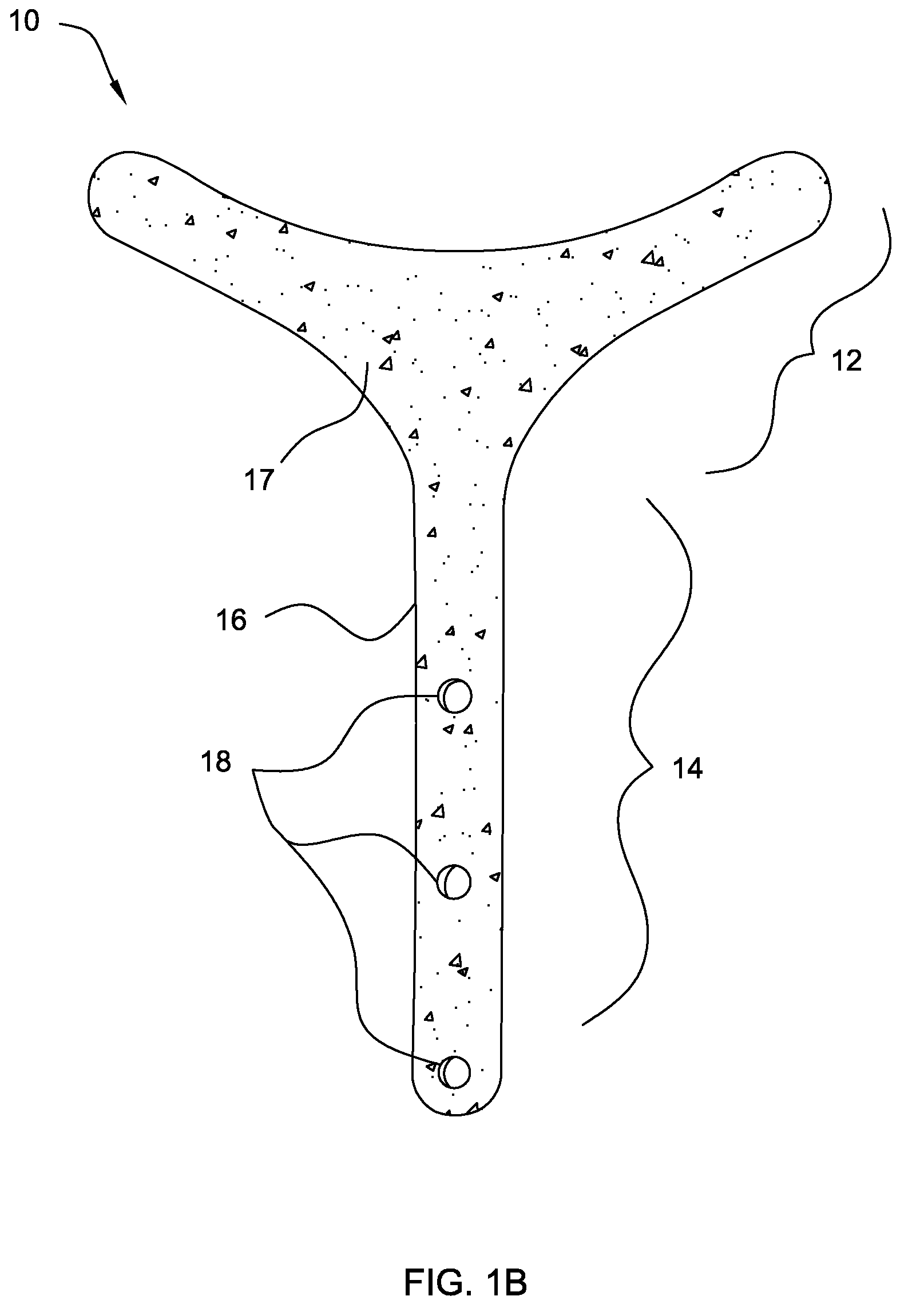
The present invention describes an implantable tissue lifting and fixation device. More particularly, the present invention describes a temporal brow lifting device comprises of a bio-absorbable supportive backing. The device has a shape of a curvilinear end and a tail end region. The curvilinear end region comprises a plurality of attachment points protruding from the supportive backing, and the tail region comprises of a plurality of cavities in order to secure the device at the desired elevated position in the deep temporal fascia. The plurality of attachment points distributes tension in a multi-vector direction over the contact area between the device and the tissue. The attachment points can be manufactured separately and attached, however, preferably, the attachment points are made integral with the temporal brow lifting device.

Description

BACKGROUND OF THE INVENTION[0001]The present invention relates to an implantable tissue lifting and fixation device. More particularly, the present invention relates to a temporal brow lifting device, which is used to lift and fix the brows at an elevated position in a brow lifting surgery and similar surgical procedures. The temporal brow lifting device of the present invention is comprised of a bio-resorbable supportive backing having a curvilinear end region and a tail end region. The curvilinear end region comprises a plurality of attachment points to facilitate brow-lift, and the tail end region having a plurality of cavities to secure the device at the desired position.[0002]The brow lift is a basic procedure for rejuvenating the upper portion of a patient's face. The brow lift procedure may be used to elevate the eyebrows, remove or lessen forehead wrinkles, reduce frown lines, smooth the nasion and elevate the nasal tip. Various surgical approaches are available for the brow...

Claims


Application Information

Patent Timeline
Patent Type & Authority Applications(United States)
IPC IPC(8): A61F2/02
CPCA61F2/0059
Inventor HENDERSON, JENIFER LEE
Owner HENDERSON JENIFER LEE
Learn More