Vitreous System

a technology of vitreous and glass plate, applied in the field of vitreous system, can solve the problems of difficult to adhere rain drops, dust or other obstacle particles to the external surface of glass plate, and the importance of through glass plate is not vital, so as to reduce the effect of reducing the frequency of dangerous manual work

Inactive Publication Date: 2008-08-28
NAKAI KOMUTEN
View PDF0 Cites 7 Cited by
  • Summary
  • Abstract
  • Description
  • Claims
  • Application Information

AI Technical Summary

Benefits of technology

[0021]Multistoried buildings including high-rise apartment or condominium buildings do usually have windowpanes positioned at such an elevation as causing acrophobia. Therefore, it also is desired to diminish frequency of dangerous manual works to cleanse the outer surfaces of those windowpanes.
[0022]The present invention addresses itself to these problems and requirements inherent in vehicles and buildings. An object of the present invention is thus to provide a novel vitreous system, that may comprise an improved glass plate. The external side of this glass plate exposed to the outside should not be apt to become dirty but be easier to cleanse, even if smudged.
[0023]Another object is to provide a vitreous system used as the front or rear glass of a vehicle and capable of automatically removing rainwater or snow that has stuck to the entire surface of its glass plate. Such a cleansing effect has to be ensured without aid of any prior art driving mechanism as employed in the known rubber or air wipers. At the same time, this vitreous system should not allow rainwater and snow to readily stick to its glass plate.
[0024]A further object is to provide a vitreous system whose glass plate is protected by nature from readily blurring due to moisture, and can be cleared instantly once and if it blurs occasionally.
[0025]A still further object is to provide a vitreous system such that any washing liquid (viz., detergent solution) is not indispensable, but can reduce frequency of occasionally using the liquid.
[0026]A yet still further object is to provide a vitreous system that may be used as the windowpane of a building such that its external surface is protected well from being rapidly smudged. It should be able to remove rainwater or snow that will have occasionally and temporarily stuck to said external surface.

Problems solved by technology

However, the sight through the glass plates are not of vital importance if buildings' windowpanes (for example, frosted glass plates) are concerned.
It will be difficult for those rain drops, dust or other obstacle particles to adhere to the external surface of glass plate.

Method used


Image

  • Vitreous System
  • Vitreous System
  • Vitreous System

Examples


Embodiment Construction

[0045]Some embodiments that will now be described referring to the accompanying drawings do not limit the present invention, but may be modified in various manners and fashions within a scope thereof.

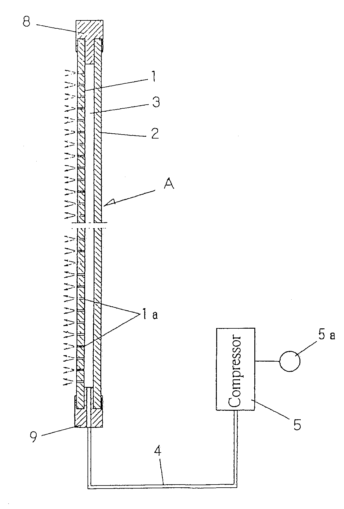
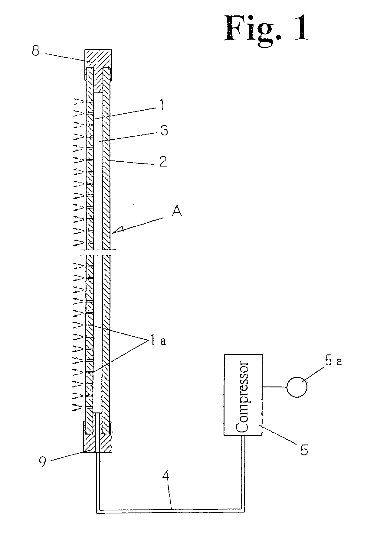
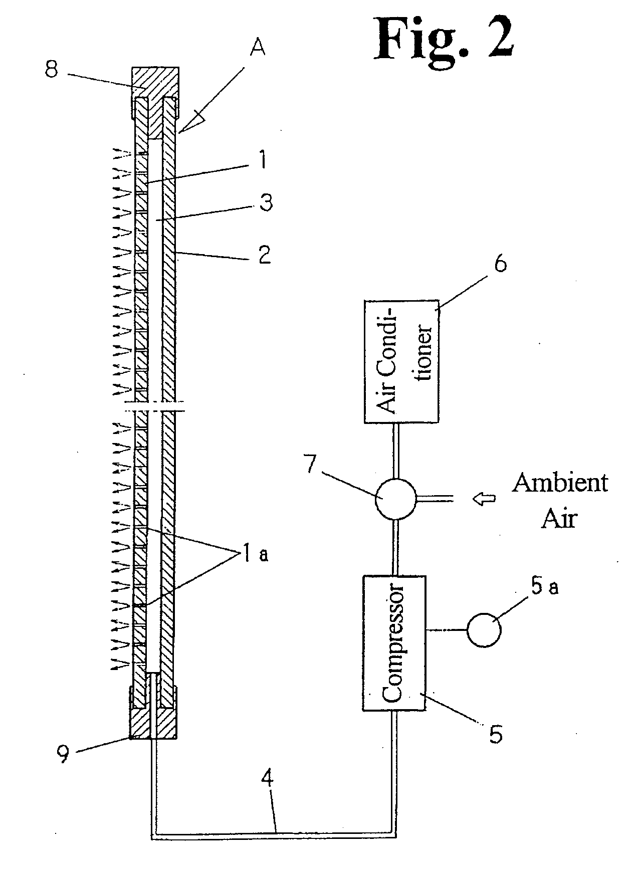
[0046]FIG. 1 illustrates partly in cross section a basic structure of the vitreous system of the invention. A laminated or multilayer vitreous body ‘A’ is composed of a transparent and perforated outside glass plate 1, and a transparent inside glass plate 2. A stratified air space 3 is defined between the outside and inside plates 1 and 2. A number of fine jetting orifices 1a formed in the outside glass plate 1 are distributed all over the surface thereof. The air space 3 intervening between those plates has a periphery that is completely sealed with a framework 8. A joint 9 is secured to a hem portion of the vitreous body and connected to a piping 4. This piping extending from a compressor 5 is in fluid communication with the air space 3 between the glass plates.

[0047]The jetting orifi...


PUM


Abstract

A vitreous system of the invention is provided for use particularly as windowpanes of a car or the like vehicle, and is always kept clean over its whole surface. A multi-layer vitreous body ‘A’ forming the system is composed of an outside glass plate (1), an inside glass plate (2) and a stratified air space (3) defined between the inside and outside plates. A number of jetting orifices (1a) are formed to penetrate the outside plate (1), and a compressor (5) is connected through a piping (4) to the air space (3) so as to charge it with a compressed air, so that this air is blown out through the orifices (1a).

Description

FIELD OF THE INVENTION[0001]The present invention relates to a vitreous system comprising glass plates and functioning to cleanse the external face (exposed to the exterior of any vehicle or building) of either glass plate to be free from rainwater, snow, condensed dew and / or blurring moisture. This system may preferably be used as the front glasses, rear glasses or other windowpanes of vehicles, the side mirrors thereof, windowpanes in buildings, or the like.BACKGROUND ART[0002]Heretofore, monolithic glass plates have been used as the windowpanes of vehicles. The inner face of a vehicle windowpane has to be protected from burring, and the air-heating and air-cooling efficiency of the vehicle interior is to be improved. Therefore, a certain proposal was made to use a double-layer window glass (exemplified in Patent Reference 1, listed below). According to this proposal, two glass plates are fixed one on another, with a hollow space being defined between them.[0003]The outer face of ...

Claims


Application Information

Patent Timeline
Patent Type & Authority Applications(United States)
IPC IPC(8): A47L1/00
CPCA47L1/00B60J1/001B60S1/54B60S1/02B60J1/002
Inventor NAKAI, AKIHIRO
Owner NAKAI KOMUTEN
Why Eureka
Try Eureka