Connection of wire to a lead frame

a technology of lead frame and wire, which is applied in the direction of contact members penetrating/cutting insulation/cable strands, casings/cabinets/drawers, electrical apparatus, etc., and can solve the problems of adding time and cos

Inactive Publication Date: 2008-08-28
CONTINENTAL AUTOMOTIVE SYST INC
View PDF18 Cites 54 Cited by
  • Summary
  • Abstract
  • Description
  • Claims
  • Application Information

AI Technical Summary

Problems solved by technology

The soldering and welding process require additional process steps such as stripping the wires for example that add time and cost.

Method used


Image

  • Connection of wire to a lead frame
  • Connection of wire to a lead frame
  • Connection of wire to a lead frame

Examples


Embodiment Construction

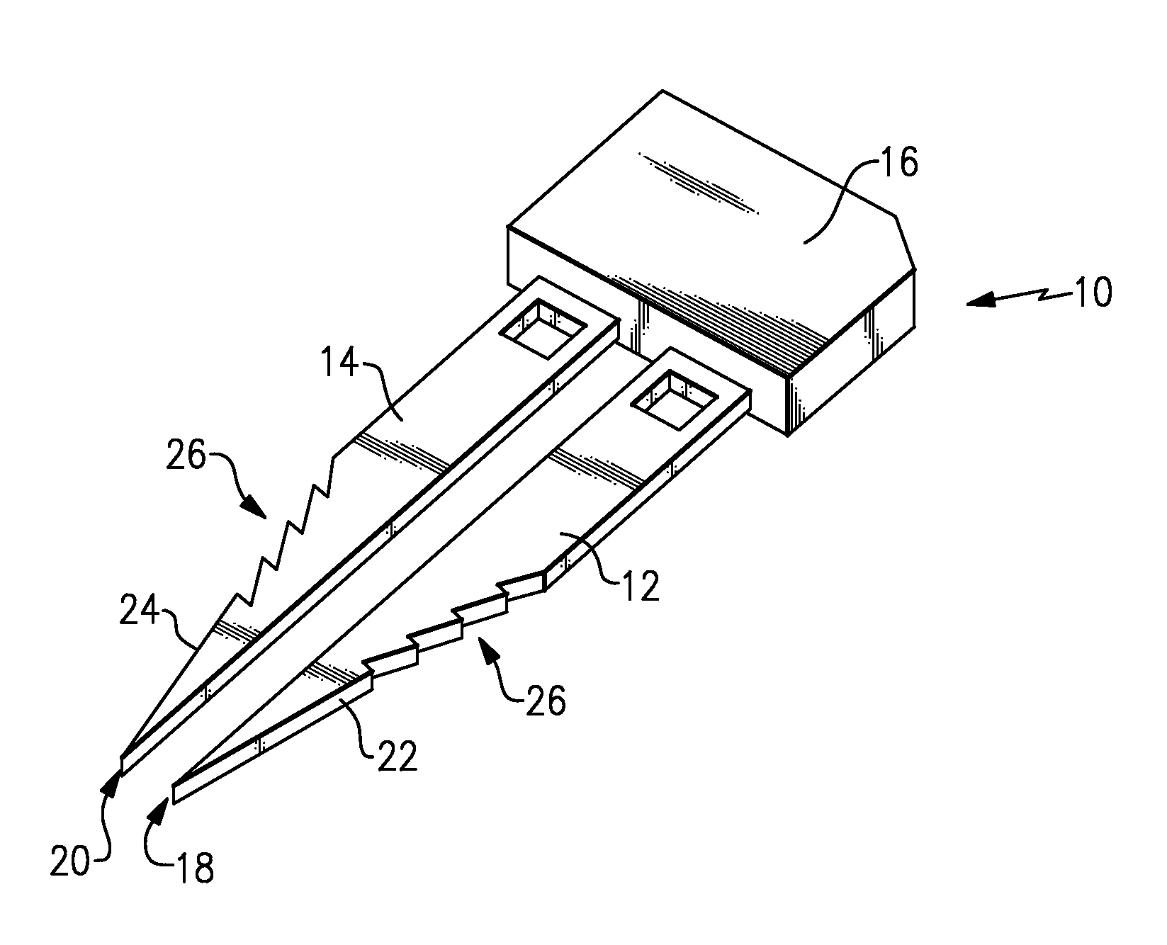
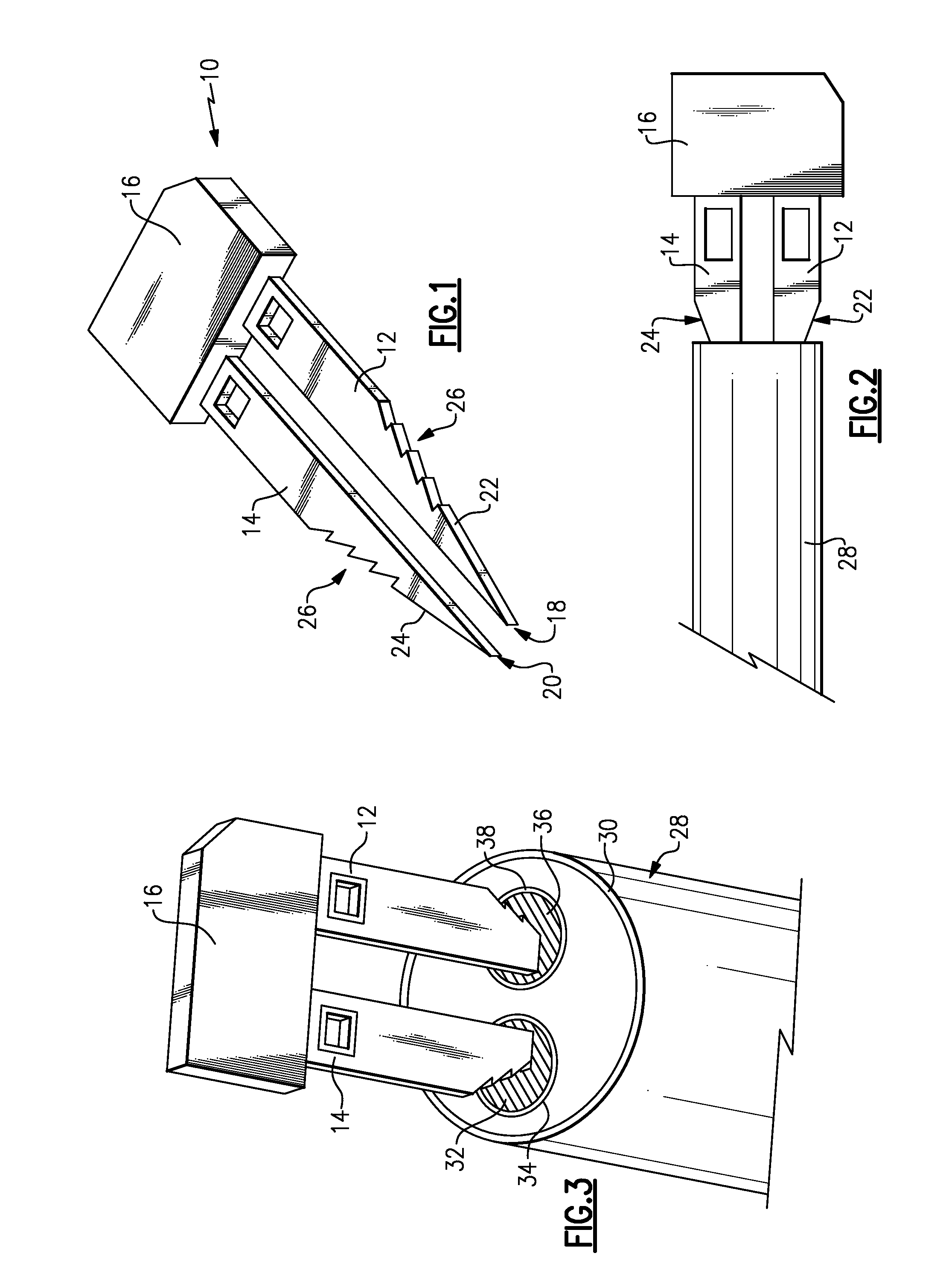
[0030]Referring to FIGS. 1-3, an integrated circuit assembly 10 includes an integrated circuit 16 encapsulated to protect the circuit components therein. Extending outwardly from the encapsulated integrated circuit 16 is a first lead frame 12 and a second lead frame 14. The first and second lead frames 12, 14 are for attachment to an electrical conduit to provide electrical communication to the circuit assembly 16. Each of the first and second lead frames 12, 14 include corresponding piercing ends 18, 20. The piercing ends 18, 20 comprise a point that provides a sharp edge for insertion into a perpendicular face of an electrical conduit such as wires within a cable jacket.

[0031]The example piercing ends 18, 20 are formed at a terminal end of angled sides 22, 24. The angled sides 22, 24 taper from a greatest width of the corresponding lead frame 12, 14 to the ends 18, 20. The piercing ends 18, 20 are intended for insertion into a perpendicular face of a wire such as for example the w...


PUM

PropertyMeasurementUnit
electrically conductiveaaaaaaaaaa
lengthaaaaaaaaaa
widthaaaaaaaaaa

Abstract

An integrated circuit includes a first lead frame and a second lead frame that extend from an overmolded circuit assembly. Each of the lead frames includes a piercing portion to pierce through insulation on a corresponding electrical conduit. The piercing portion of the lead frames also provides a wrap around feature to mechanically secure the wire to the corresponding electrical conduit. In this manner, several processes can be eliminated and are not required for the desired mechanical and electrical connection of the integrated circuit lead frame to corresponding electrical conductors.

Description

CROSS REFERENCE TO RELATED APPLICATION[0001]The application claims priority to U.S. Provisional Application Nos. 60 / 891,597 and 60 / 891,609 both filed on Feb. 26, 2007.BACKGROUND OF THE INVENTION[0002]This invention generally relates to a method of attaching a wire to a lead frame. More particularly, this invention relates to a method and lead frame for attaching a wire to the lead frame without soldering or welding.[0003]An integrated circuit typically includes stamped metal leads for providing a desired electrical connection. In a common configuration, a positive lead and a negative lead extend from an overmolded integrated circuit. The metal leads are utilized to provide the desired electrical connections to the integrated circuit. In some applications, it is desired to mount the integrated circuit in locations remote from a circuit board. In such applications, electrical communication is provided by wires that are soldered or welded to the corresponding leads. The soldering and w...

Claims


Application Information

Patent Timeline
Patent Type & Authority Applications(United States)
IPC IPC(8): H05K7/02H05K13/04H05K7/18
CPCY10T29/5313H01R4/26
Inventor VICH, GAETAN
Owner CONTINENTAL AUTOMOTIVE SYST INC
Why Eureka
Try Eureka