
Device and Method For Thermophoretic Fluid Delivery

a technology of thermophoretic fluid and device, which is applied in the field of thermophoretic fluid delivery device, can solve the problems of high cost of power module, time required for medication absorption, and discomfort level, and achieve the effect of low cost, fast and accura

Inactive Publication Date: 2008-08-28
MICROLIN
View PDF11 Cites 106 Cited by
  • Summary
  • Abstract
  • Description
  • Claims
  • Application Information

AI Technical Summary

Benefits of technology

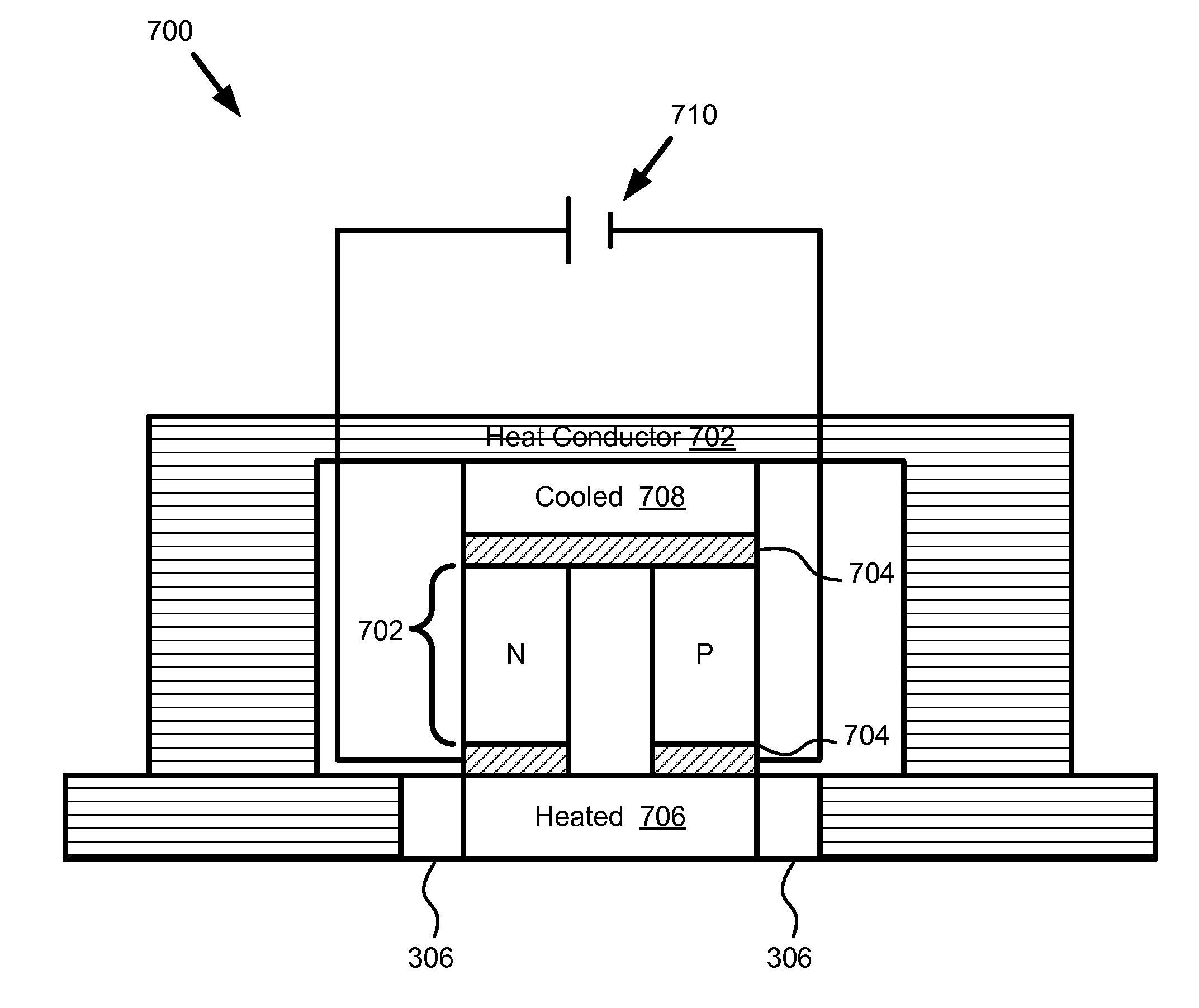
[0010]The invention provides a method for delivering a treatment to a body by way of an thermophoretic transport procedure and device. A device constructed according to principles of the instant invention provides a low cost, disposable, single use, fast and accurate, thermophoretic fluid delivery device for external or implantable use. A body may be construed specifically as a mammalian (e.g. human or animal) body, or alternatively and generally, as a container of an electrolyte.
[0014]A method is also provided that includes generating a hot dermal region and transdermally delivering a beneficial agent, insulating, generating a cold dermal region, and creating a thermal potential across the hot dermal region and the cold dermal region. The method may also include transferring one of heat and cold to the cold dermal region, stretching the hot dermal region and increasing transdermal delivery rates of the beneficial agent. Furthermore, the method may include preparing skin to receive the beneficial agent, and penetrating the skin.

Problems solved by technology

While treatment time requirements for devices having auxiliary power modules are generally reduced, the power modules are expensive, and so typically must be reused.
However, iontophoretic devices of both types described above can cause a level of discomfort in the patent depending upon the voltage applied and the sensitivity of the patient.
The drawback to this approach is the time required to absorb the medication when no driving force is present.
Other limitations include the wide variability of skin permeability among patients, thereby making it nearly impossible to deliver a drug in a consistently timely manner to all types of patients.
However, current heated patches are limited by the temperature a patient can comfortably tolerate (about 60 degrees Celsius).

Method used


Image

  • Device and Method For Thermophoretic Fluid Delivery
  • Device and Method For Thermophoretic Fluid Delivery
  • Device and Method For Thermophoretic Fluid Delivery

Examples


Embodiment Construction

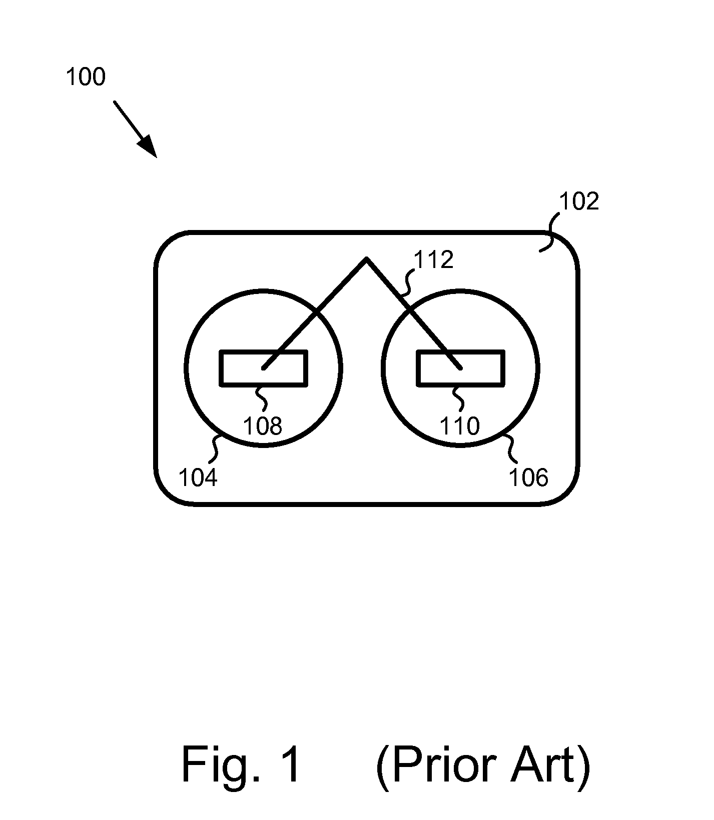
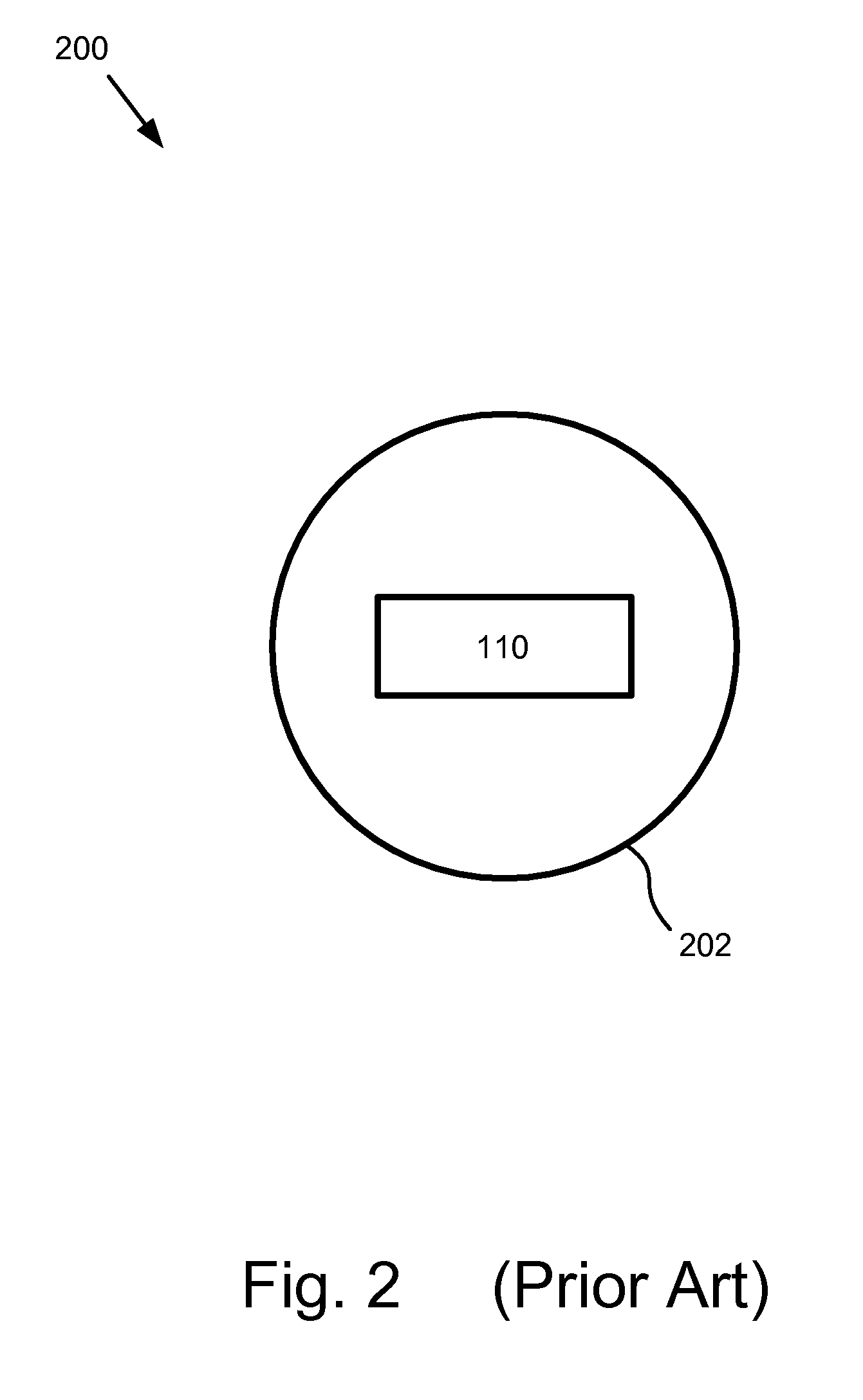
[0026]The presented embodiments of the present invention will be best understood by reference to the drawings, wherein like parts are designated by like numerals throughout. It will be readily understood that the components of the present invention, as generally described and illustrated in the figures herein, could be arranged and designed in a wide variety of different configurations. Thus, the following more detailed description of the embodiments of the thermophoretic device of the present invention, as represented in FIGS. 1 through 9, is not intended to limit the scope of the invention, as claimed, but is merely representative of presently preferred embodiments of the invention.

[0027]Reference will now be made to the drawings in which the various elements of the invention will be given numerical designations and in which the invention will be discussed so as to enable one skilled in the art to make and use the invention. It is to be understood that the following description is...


PUM


Abstract

A method and device for thermolphoretic fluid or drug delivery through the creation of a thermal gradient in the skin. The device includes a heat generating mechanism capable of transdermal delivery of a beneficial agent, an insulating portion coupled with the heat generating mechanism, a cold generating mechanism coupled with the insulating portion, and wherein the heat generating mechanism and the cold generating mechanism create a thermal potential across dermal regions. The method includes generating a hot dermal region and transdermally delivering a beneficial agent, insulating, generating a cold dermal region, and creating a thermal potential across the hot dermal region and the cold dermal region.

Description

RELATED APPLICATIONS[0001]This application is related to and claims the benefit of U.S. Provisional Patent Application Ser. No. 60 / 891,712 entitled “THERMALPHORETIC FLUID DELIVERY DEVICE AND METHOD” and filed on Feb. 26, 2007 for Ashok V. Joshi, which is incorporated herein by reference.FIELD OF THE INVENTION[0002]The present invention relates to a device and method for delivering drugs or other beneficial agents. More specifically, the present invention relates to thermophoretic transport devices and methods of their use in delivering treatment to a body.BACKGROUND OF THE INVENTION[0003]Different methods for drug administration have long been known in the practice of medicine. These methods of drug administration include oral consumption of the drug, injections of the drug by needle, and transdermal administration of the drug, etc. The transdermal administration of drugs, beneficial agents, and pharmaceutically active agents is achieved by the direct application of the drug to the ...

Claims


Application Information

Patent Timeline
Patent Type & Authority Applications(United States)
IPC IPC(8): A61M39/00
CPCA61M37/00A61M2037/0007A61M37/0015
Inventor JOSHI, ASHOK V.
Owner MICROLIN
Learn More