Locking fixation system and lag tool

a fixation system and tool technology, applied in the field of locking fixation system and lag tool, can solve the problems of inability to induce compression (lag) limited engagement of the screw head, and inability to induce lag across the fracture plane, so as to facilitate the insertion of the fixation element and reduce the interference of the fixation devi

Inactive Publication Date: 2008-08-28
SMALL BONE INNOVATIONS
View PDF49 Cites 83 Cited by
  • Summary
  • Abstract
  • Description
  • Claims
  • Application Information

AI Technical Summary

Problems solved by technology

However, both of these locking mechanisms have drawbacks.
A disadvantage of the mechanism described in the '553 and '881 patents is the inability to induce compression (lag) across a fracture plane.
In the mechanism taught in the '461 patent, the thread on the head of the screw is limited in its ability to engage the plate and is also associated with an increased risk of gauling (cold welding) of the screw to the bone plate.
However, such a requirement imposes needless plate design constraints and leads to increased manufacturing costs.

Method used


Image

  • Locking fixation system and lag tool
  • Locking fixation system and lag tool
  • Locking fixation system and lag tool

Examples


Embodiment Construction

[0027]The present invention is described more fully hereinafter with reference to the accompanying drawings, which form a part hereof, and which show, by way of illustration, specific exemplary embodiments by which the invention may be practiced. This invention may, however, be embodied in many different forms and should not be construed as limited to the embodiments set forth herein; rather, these embodiments are provided so that this disclosure will be thorough and complete, and will fully convey the scope of the invention to those skilled in the art. Moreover, the present invention may be embodied as methods or devices. Accordingly, the present invention may take the form of an entirely mechanical device embodiment, an entirely method embodiment or an embodiment combining method and mechanical device aspects. The following detailed description is, therefore, not to be taken in a limiting sense.

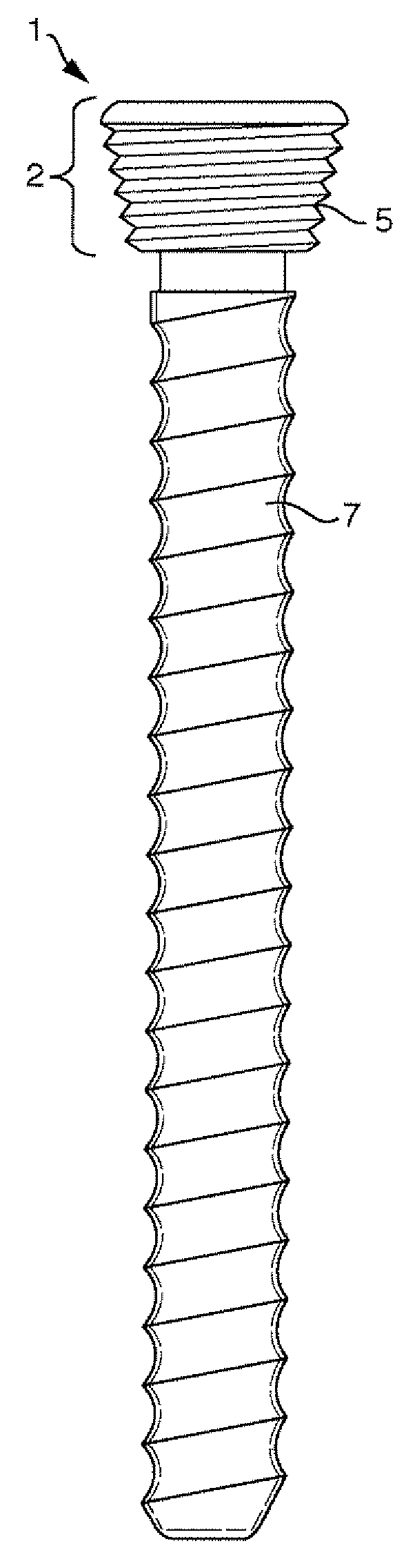
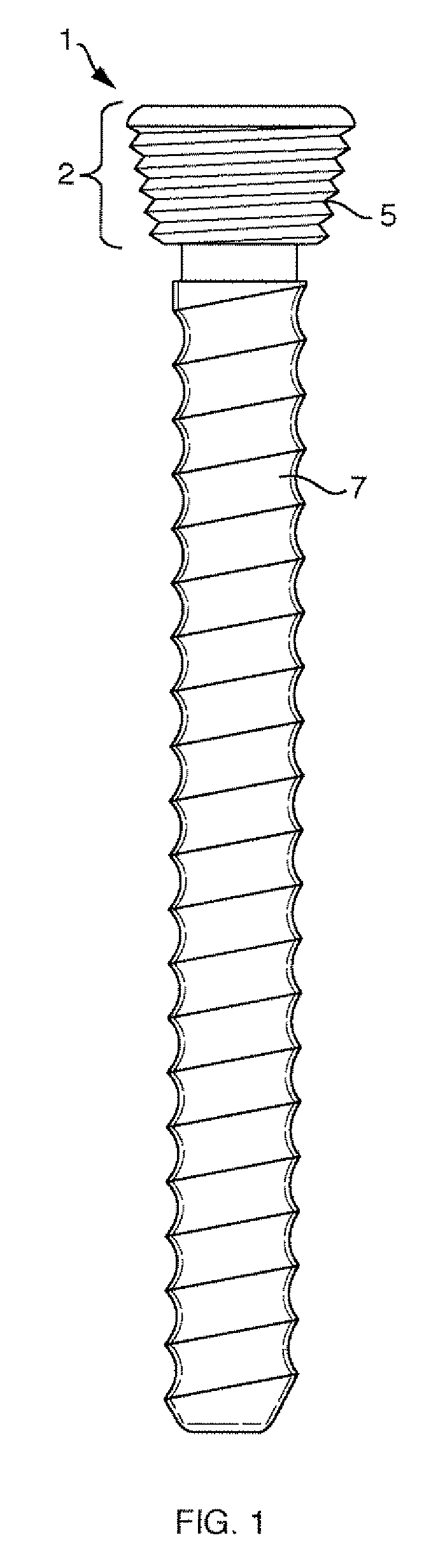
[0028]Locking Fixation System

[0029]The present invention relates to a locking fixation ...


PUM


Abstract

The present application relates to a locking bone fixation device having tabs to engage the threads of an orthopedic fixation element. A tool and method for inducing compression across a fracture plane is also disclosed.

Description

CROSS-REFERENCE TO RELATED APPLICATIONS[0001]This application claims the benefit of U.S. Provisional Application Nos. 60 / 875,689 filed on Dec. 19, 2006, and 60 / 975,936 filed on Sep. 28, 2007, the contents of which are hereby incorporated by reference in their entirety.BACKGROUND[0002]Bone plates are commonly used to assist in the healing of broken and fractured bones, especially in situations where casts cannot be applied to the injured area (e.g., fractures occurring to facial areas such as the nose, jaw or eye sockets). A fractured or broken bone may first need to be reset into its proper position before the fracture site is held in place by a bone plate secured to the bone with a screw or other type of fastener.[0003]Some bone plates have a locking mechanism to lock the fastener to the bone plate: e.g., those described in U.S. Pat. No. 5,601,553 to Trebling et al., U.S. Pat. No. 6,206,881 to Frigg, et al., and U.S. Pat. No. 6,974,461 to Wolter, each of which is hereby incorporate...

Claims


Application Information

Patent Timeline
Patent Type & Authority Applications(United States)
IPC IPC(8): A61B17/58A61B17/56
CPCA61B17/8057A61B17/88A61B17/863
Inventor GILBERT, STEPHENLORING, THOMASMINIER, JOHN
Owner SMALL BONE INNOVATIONS
Why Eureka
Try Eureka