
Channel change latency reduction

a channel change and latency reduction technology, applied in the field of wireless communication systems, can solve the problems of not offering power savings, reducing the battery life of receivers, and undesirable to monitor and store all available channels, so as to reduce channel change latency and quickly see contents

Inactive Publication Date: 2008-08-28
MAXLINEAR INC
View PDF18 Cites 49 Cited by
  • Summary
  • Abstract
  • Description
  • Claims
  • Application Information

AI Technical Summary

Benefits of technology

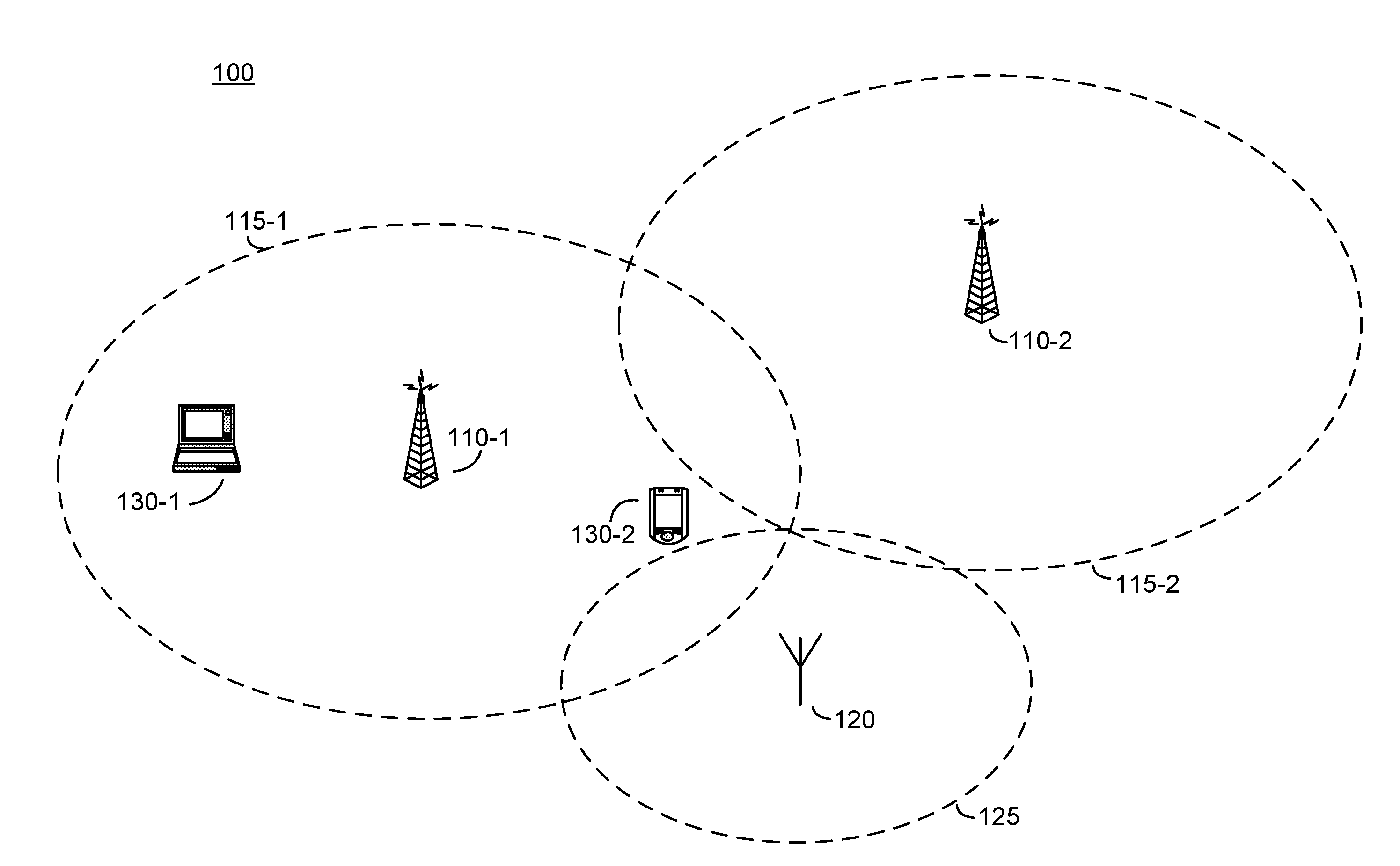
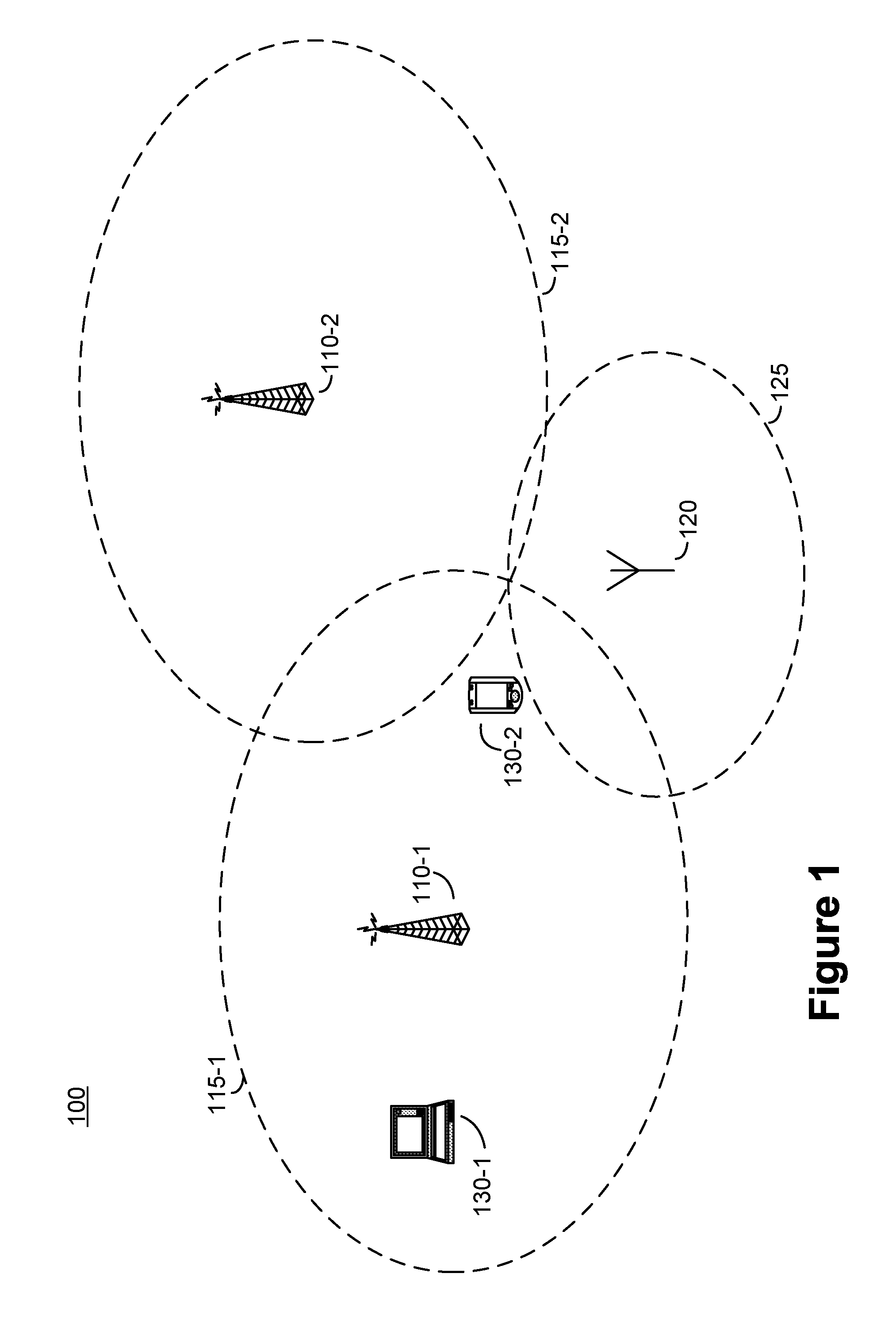
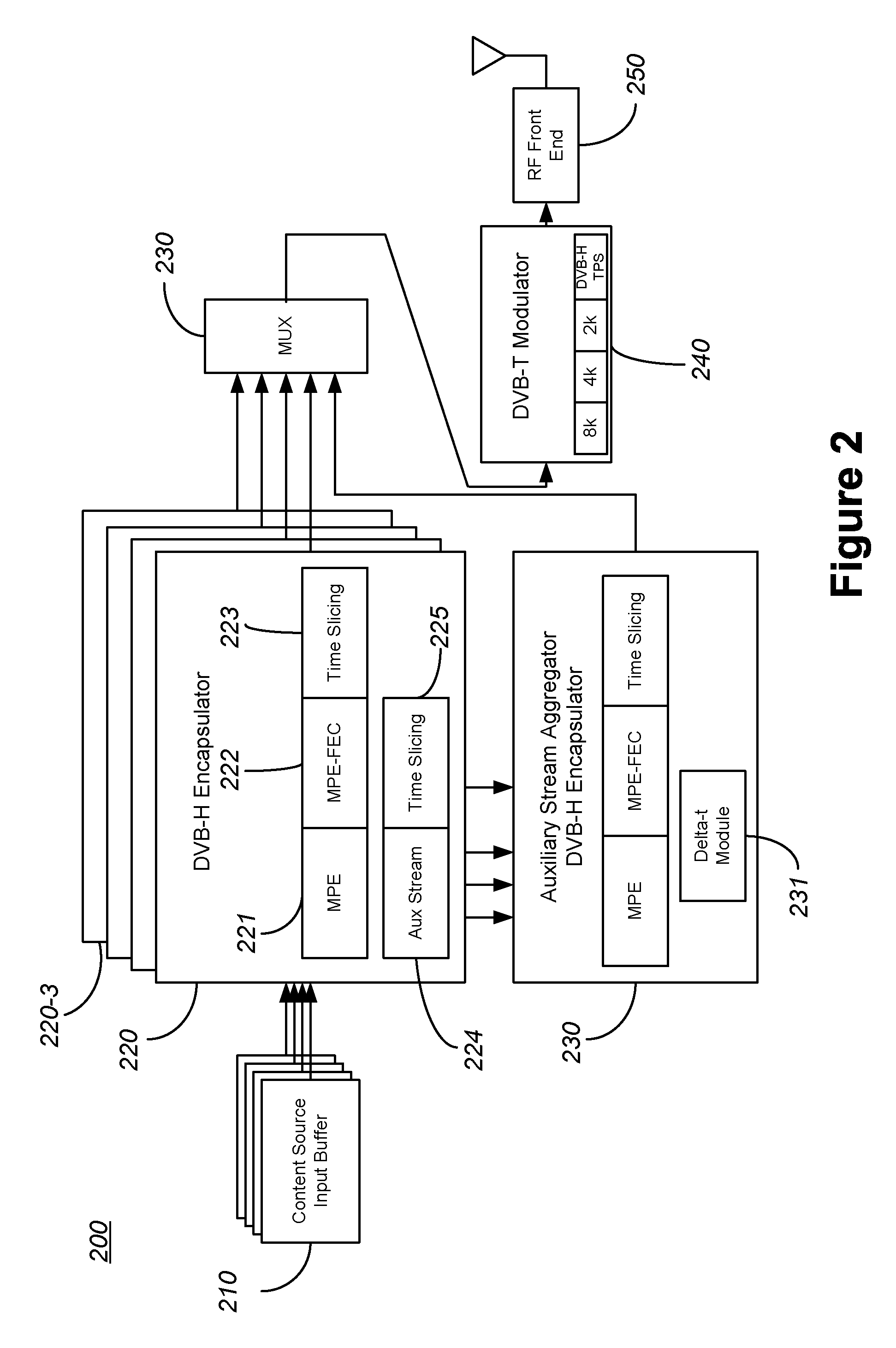
[0009]In accordance with one embodiment of the present invention, low-latency channel surfing in a wireless communication system is achieved, thus enabling the content viewer to quickly see the contents carried over a selected channel while searching channels for the desired content. In one embodiment, the wireless communication system is a DVB-H system. Apparatus and methods for reducing channel change latency in, for example, a DVB-H system may be implemented in a transmitter, receiver, or in a combination of transmitter and receiver. The transmitter may be configured to generate and transmit one or more auxiliary streams or channels, where each auxiliary channel contains reduced resolution content corresponding to one or more channels. The receiver may be configured to process the one or more auxiliary channels to present the reduced resolution content while processing the full resolution channel for display. The receiver may be configured to cache portions of content from one or more non-selected channels. The receiver presents the cached content when the channel is selected while concurrently searching and processing the full resolution channel content.

Problems solved by technology

It is typically undesirable to monitor and store all available channels, because of the amount of memory needed to support all channels.
Additionally, the receiver would suffer from reduced battery life, because the receiver would need to monitor all time slices and thus could not offer any power savings available through time slicing.

Method used


Image

  • Channel change latency reduction
  • Channel change latency reduction
  • Channel change latency reduction

Examples


Embodiment Construction

[0019]Effective or actual channel change latencies are reduced in a communication system by implementing optimizations in a broadcast transmitter, a receiver, or in a combination of broadcast transmitter and receiver. One such communication system is a DVB-H communication system.

[0020]In accordance with one embodiment of the present invention, a broadcast transmitter is adapted to transmit one or more auxiliary streams. Each auxiliary stream includes reduced resolution content corresponding to the full resolution content carried on one or more channels. The reduced resolution content may be generated by reducing the quality of images, by reducing the frame rate of video content, increasing compression ratios, and the like, or some combination thereof. For example, an auxiliary stream may be configured to carry a reduced resolution version of a single corresponding primary stream or channel. The auxiliary stream may be configured with a time slice that is the same or different from t...


PUM


Abstract

A wireless communication system is enhanced to allow for low-latency channel surfing and to enable a user to quickly see the content carried over a selected channel while searching channels for desired content. The techniques for reducing the channel change latency may be implemented in a transmitter, receiver, or in a combination of transmitter and receiver. The wireless communication system is optionally a DVB-H communication system. The transmitter may generate and transmit one or more auxiliary channels, where each auxiliary channel contains reduced resolution content corresponding to one or more channels. The receiver may process the one or more auxiliary channels to present the reduced resolution content while processing the full resolution channel for display. The receiver caches portions of content from one or more non-selected channels and presents the cached content when the channel is selected while concurrently searching and processing the full resolution channel content.

Description

CROSS-REFERENCES TO RELATED APPLICATIONS[0001]The present application claims benefit under 35 USC 119(e) to U.S. Provisional Application No. 60 / 891,460, filed on Feb. 23, 2007, entitled “Channel Change Latency Reduction In DVB-H Receivers”, the contents of which is incorporated herein by reference in its entirety.BACKGROUND OF THE INVENTION[0002]The present invention relates to wireless communication systems, and more particularly to reducing the latency experienced by users whilst scanning through available content, such as television programs, in a DVB-H based wireless communication system.[0003]A wireless communication system implementing Digital Video Broadcasting for Handheld (DVB-H) typically offers a variety of programming (content) for presentation to a user of a mobile receiving device. The content typically includes video content to be displayed on the mobile receiver, but in general, the content carried in any particular channel is not limited to content or media having a...

Claims


Application Information

Patent Timeline
IPC IPC(8): H04N7/16
CPCH04H20/26H04H20/40H04N21/4384H04H60/43H04N21/41407H04H60/11
Inventor RAMESH, SRIDHARLING, CURTISAKELLA, RAMAKRISHNALEE, BRENNDON
Owner MAXLINEAR INC
Learn More