Temporary movable/removable compression partition wall system

Inactive Publication Date: 2008-09-04
WEBB SCOTT T
View PDF12 Cites 39 Cited by
  • Summary
  • Abstract
  • Description
  • Claims
  • Application Information

AI Technical Summary

Benefits of technology

[0024]An additional object is to provide a temporary compression partition wall formed of light weight panels that can be easily and quickly connected by their side edges to have a wall of desired length. In a preferred embodiment each two adjacent panel edges fit into opposite sides of a ver

Problems solved by technology

1. Residual damage to the ceiling, floor and/or walls after removal of the temporary wall, requiring plastering, painting and/or other surface repairs and finishing.
2. The expensive cost of assembly and erection of temporary walls because of the requirement for a professional installer.
3. The expensive cost of the temporary wall components.
4. The cost of transporting and/or storing the relatively heavy wall components.
5. The difficulty or impossibility for residential tenants to do their own assembly because it is too heavy and/or complicated.
6. The difficulty a

Method used


Image

  • Temporary movable/removable compression partition wall system
  • Temporary movable/removable compression partition wall system
  • Temporary movable/removable compression partition wall system

Examples


Embodiment Construction

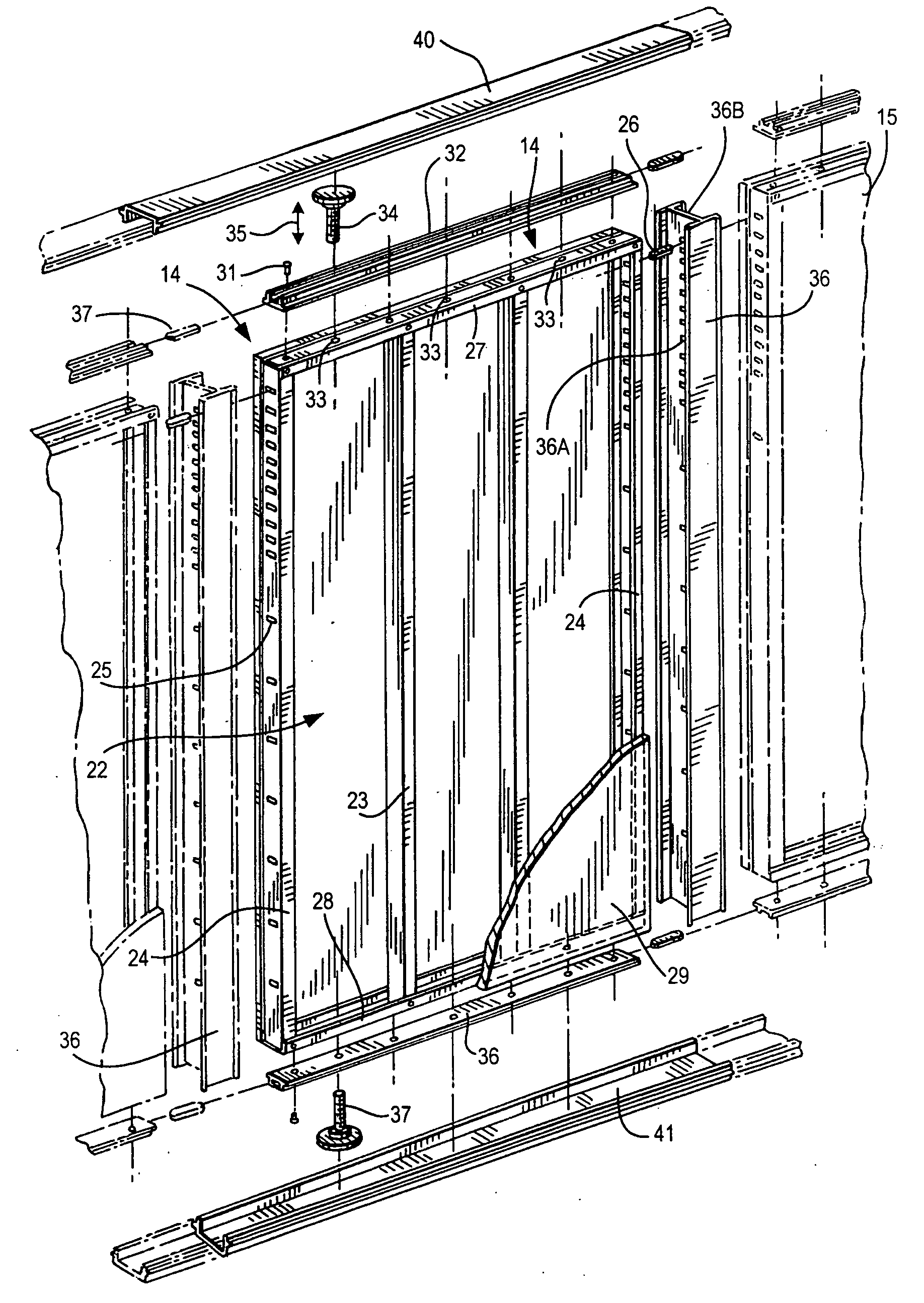
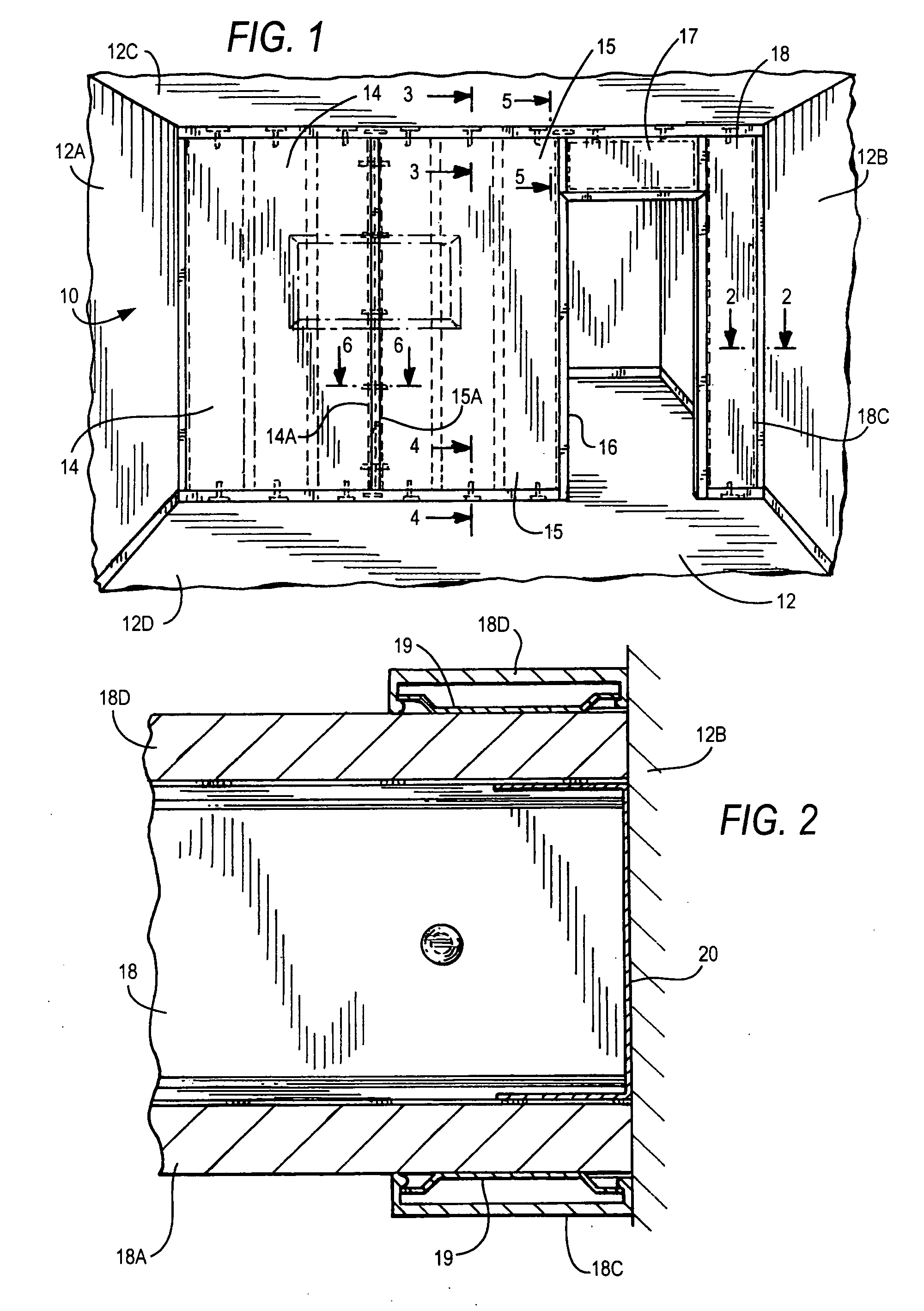
[0046]FIG. 1 shows an installation of a temporary pressurized wall 10 of my movable / removable compression partition system where the new wall partitions a room 12 into separate parts. Wall 10 is formed of two 8′×4′ panels 14 and 15, plus door frame 16, header panel 17 above the door frame 16 and filler panel 18. As indicated in FIG. 1, panels 14 and 15 are detachably joined together along their adjacent side edges 14A and 15A, as will be described later in detail. Panel 15 is similarly removably attached to panel 17, and panel 17 is removably attached to panel 18. Room 12 includes side walls 12A and 12B, ceiling 12E and floor 12D. Wall 10 has top part 10A which removably engages ceiling 10C, and bottom part 10B which removably engages floor 12D.

[0047]FIG. 2 is a top plan view in section of panel 18 engaging the room's side wall 12B. Panel 18, while narrower than basic panel 14, has certain typical construction features, such as front and rear panel faces 18A and 18B, front and rear ...


PUM


Abstract

A temporary movable/removable compression partition wall system for partitioning a room includes a wall component and spaced-apart pressure feet at the top of the wall for pressing against a track positioned between the top of the wall and the ceiling and additional spaced-apart pressure feet at the bottom of the wall for pressing against a track positioned between the bottom of the wall and the floor. This wall is temporarily, securely and rigidly positionable at a selected location in a room and subsequently removable with substantially no damage to the ceiling, floor or walls.

Description

BACKGROUND[0001]1. Field of the Invention[0002]The field of this invention is partition wall systems where a temporary wall is positioned to partition a room into separated parts. Such systems are applicable and highly useful in residential apartments and homes, lofts, offices, theaters, schools, hospitals, gymnasiums and other institutional, commercial and industrial buildings.[0003]2. Prior Art[0004]Need for temporary partitioning of space occurs in countless situations, as when separate spaces are needed within a given room or when a particular room is too large for the desired use, and specifically in residential apartments and homes where the total space is limited and within that space an additional bedroom, storage, den or other work space is temporarily needed.[0005]As indicated above, the field of this invention is temporary partition wall systems where it is contemplated that a temporary wall will, at a future date, be removed or moved. Common and typical problems associat...

Claims


Application Information

Patent Timeline
IPC IPC(8): E06B9/06
CPCE04B2002/749E04B2/821
Inventor WEBB, SCOTT T.
Owner WEBB SCOTT T
Why Eureka
Try Eureka