Key Actuation Mechanism

a technology of actuation mechanism and key, which is applied in the direction of wing knob, building lock, construction, etc., can solve the problems of not having the appropriate visibility, difficulty in grasping and rotating the key, and considerable room in the art for further improvements of such devices, mechanisms and arrangements, etc., to achieve easy grasping, simple positioning of the key in the keyhole, and pain relief

Inactive Publication Date: 2008-09-04
RUSSO AMATI NATALEE
View PDF19 Cites 3 Cited by
  • Summary
  • Abstract
  • Description
  • Claims
  • Application Information

AI Technical Summary

Benefits of technology

[0009]Accordingly, it is one object of the present invention to provide a key actuation mechanism that overcomes the drawbacks and deficiencies of the prior art. It is another object of the present invention to provide a key actuation mechanism that allows for the mechanical or automated movement or rotation of a key within a keyhole for unlocking a lock mechanism. It is a further object of the present invention to provide a key actuation mechanism that provides light to a typically darkened area. It is yet another object of the present invention to provide a key actuation mechanism that alleviates the pain and discomfort associated with moving the key within the keyhole. It is a still further object of the present invention to provide a key actuation mechanism that is easily grasped and provides for the simple positioning of the key in the keyhole.

Problems solved by technology

In many instances, a user may approach the door, but not have the appropriate visibility to insert the key in the keyhole.
Certain persons may have trouble grasping and rotating the key due to a variety of constraints, e.g., physical limitations, clothing (gloves), etc.
However, there remains considerable room in the art for further improvements of such devices, mechanisms and arrangements.
For example, one drawback associated with the above-mentioned devices, mechanisms and arrangements is the manual nature of the key-turning or actuation operation.
Many people have certain limitations, e.g., age, physical, etc., which makes the turning motion required to rotate the key after insertion in the keyhole difficult and / or painful.
For example, people with physical disabilities, such as the elderly, the handicapped or those recovering from injuries or surgery encounter difficulties while performing tasks that most of us take for granted, i.e., turning a key in a lock.
Additionally, those suffering from carpal tunnel syndrome find such movements extremely difficult as well.
None of the prior art devices, mechanisms and arrangements alleviates the manual hand motion, movement or rotation required to unlock the lock mechanism with such a key.

Method used


Image

  • Key Actuation Mechanism
  • Key Actuation Mechanism

Examples


Embodiment Construction

[0016]For purposes of the description hereinafter, the terms “upper”, “lower”, “right”, “left”, “vertical”, “horizontal”, “top”, “bottom”, “lateral”, “longitudinal” and derivatives thereof shall relate to the invention as it is oriented in the drawing figures. However, it is to be understood that the invention may assume various alternative variations and step sequences, except where expressly specified to the contrary. It is also to be understood that the specific devices and processes illustrated in the attached drawings, and described in the following specification, are simply exemplary embodiments of the invention. Hence, specific dimensions and other physical characteristics related to the embodiments disclosed herein are not to be considered as limiting.

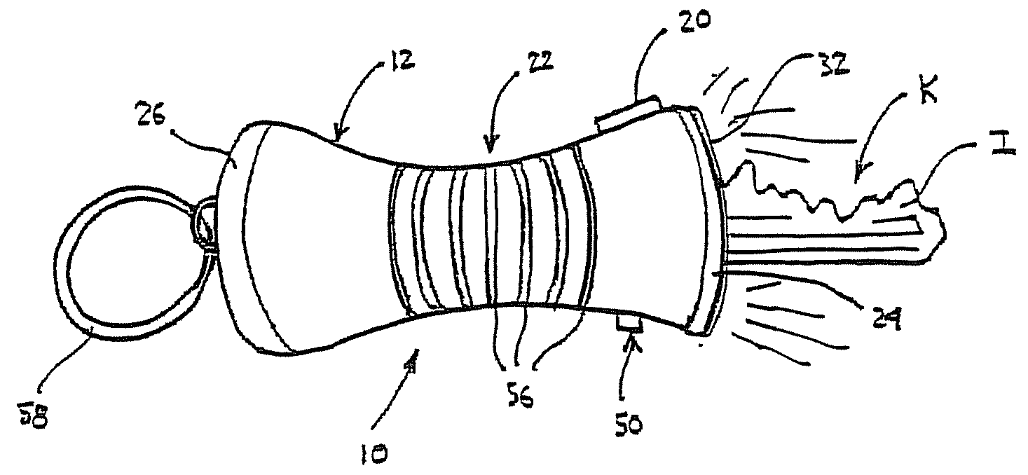
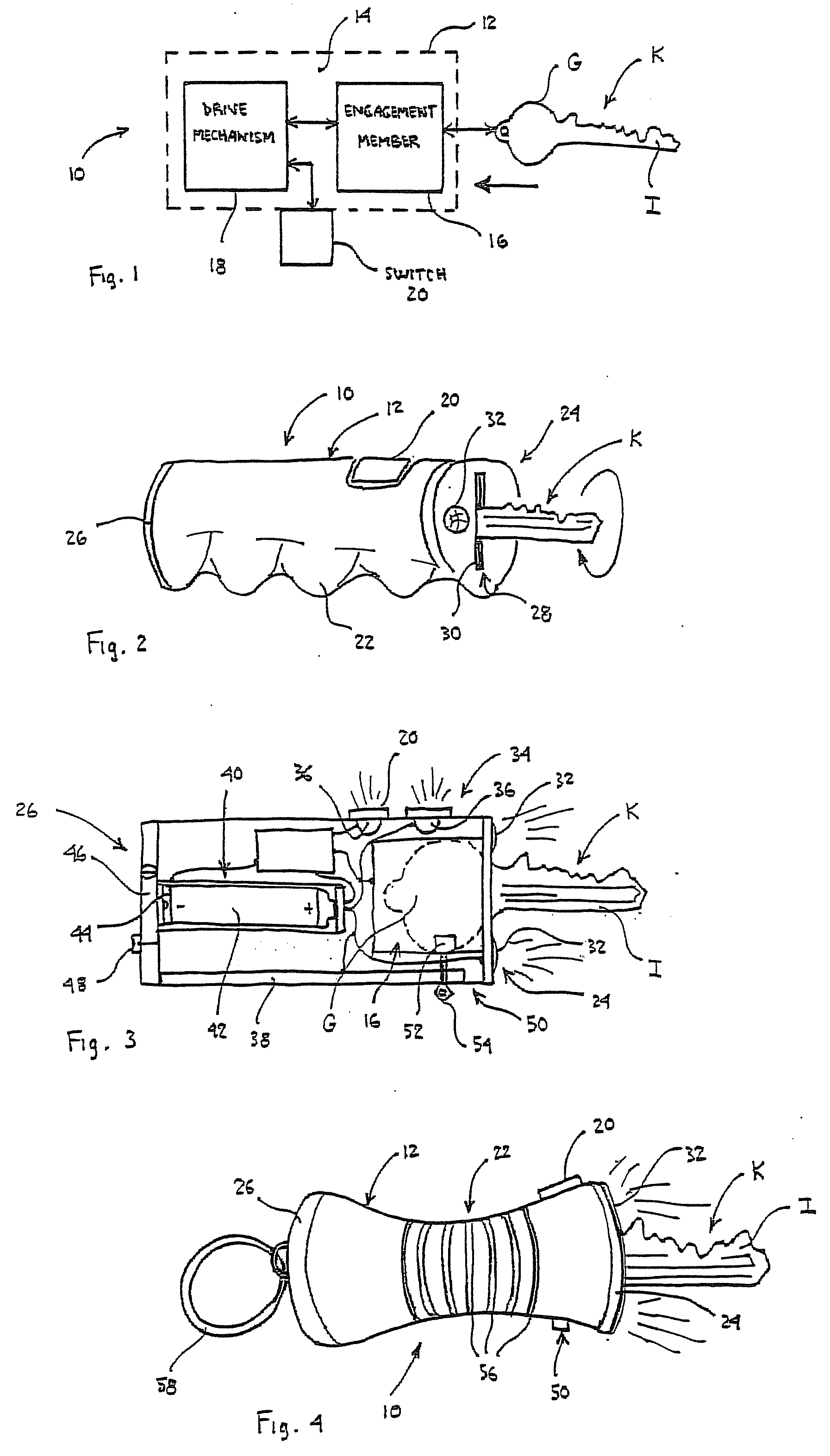
[0017]The present invention is directed to a key actuation mechanism 10, as illustrated in various embodiments and in use in FIGS. 1-4. The key actuation mechanism 10 is useful in connection with a variety of lock mechanisms (n...


PUM


Abstract

A key actuation mechanism for mechanically moving a key having a grip end and an insertion end, the mechanism comprising: a housing; a key engagement member configured to releasably engage the grip end of the key, the engagement member moveable with respect to at least a portion of the housing; a drive mechanism in electrical communication with the key engagement member and configured to drive movement of the engagement member; and a switch in communication with the drive mechanism, the switch operable to activate the drive mechanism, which causes the engagement member to move.

Description

CROSS REFERENCE TO RELATED APPLICATIONS[0001]This application claims the benefit of priority of U.S. Provisional Patent Application No. 60 / 904,526, filed Mar. 2, 2007, which is incorporated herein by reference in its entirety.BACKGROUND OF THE INVENTION[0002]1. Field of the Invention[0003]The present invention relates generally to devices for use in assisting persons with limited movement or other constraints and, in particular, to a key actuation mechanism and device for assisting a user with automated movement of a key within a lock mechanism.[0004]2. Description of the Related Art[0005]Presently, and in order to access secure areas, locks are normally used. For example, in order to access one's dwelling or home, the doors normally have a lock mechanism that bolts or otherwise renders the door immovable, except through the use of a key. Therefore, in order to gain access to the area behind the door, a person will insert the key into a keyhole extending into the lock mechanism. Nex...

Claims


Application Information

Patent Timeline
Patent Type & Authority Applications(United States)
IPC IPC(8): E05B65/00
CPCE05B1/0053E05B17/103E05B2047/0017E05B47/0012E05B19/00E05B2047/0083Y10T70/50
Inventor RUSSO-AMATI, NATALEE
Owner RUSSO AMATI NATALEE
Why Eureka
Try Eureka