Polarization Maintaining Fiber Pigtail Assembly

a technology of maintaining fiber and pigtail, which is applied in the direction of optical fiber with polarisation, instruments, optical light guides, etc., can solve the problems of increasing the manufacturing cost and affecting the quality of the final optical modul

Active Publication Date: 2008-09-04
LUMENTUM OPERATIONS LLC
View PDF22 Cites 9 Cited by
  • Summary
  • Abstract
  • Description
  • Claims
  • Application Information

AI Technical Summary

Benefits of technology

[0015]In accordance with the invention, an optical fiber pigtail assembly is provided, which comprises a mounting pad, a polarisation maintaining (PM) optical fiber having a fast polarisation axis and a slow polarisation axis orthogonal to the fast polarization axis, and an end for optically coupling the PM optical fiber to an optical component; the PM optical fiber is soldered directly to the mounting pad near the end of the PM optical fiber without a sleeve therebetween in a vertical slow axis orientation, so that the fast polarization axis is generally parallel to the mounting pad and wherein the slow polarization axis is generally orthogonal to the mounting pad.

Problems solved by technology

However, one drawback of this procedure is that a PER degradation may occur because it is difficult to precisely position a PM fiber at the center of the sleeve.
These types of pigtail assemblies, although appearing to perform their intended function, are however significantly more complex in fabrication than the direct soldering of fiber to a mounting pad, require non-standard components such as elliptical ferrules and sleeves to ensure that the PER is not degraded, and significantly add to the manufacturing costs of the final optical module.

Method used


Image

  • Polarization Maintaining Fiber Pigtail Assembly
  • Polarization Maintaining Fiber Pigtail Assembly
  • Polarization Maintaining Fiber Pigtail Assembly

Examples


Embodiment Construction

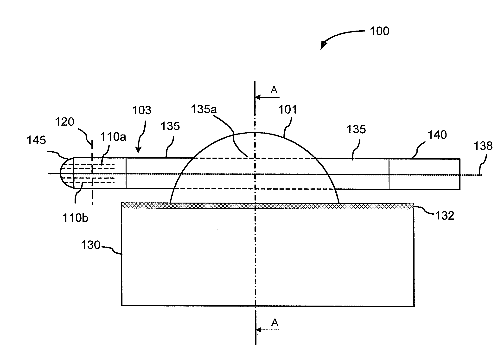
[0029]An exemplary embodiment of the PM optical fiber pigtail assembly of the present invention is illustrated in FIGS. 3 and 4 and will now be described.

[0030]Referring first to FIG. 3, the PM optical fiber pigtail assembly (PMFA) 100 includes a PM optical fiber (PMF) 103, which is soldered directly to a mounting pad 130 without a sleeve or a ferrule around the PMF 103 separating it from the mounting pad 130. The PMF 103 has an end 145 for coupling to an optical component (not shown), the end 145 of the PMF 103 being also referred to hereinafter as the proximate fiber end 145 or simply as the proximate end 145. A portion 135a of the PMF 103 near the proximate fiber end 145 is embedded in a solder ball 130, which adheres to both the PMF 103 and the mounting pad 130 and fixedly attaches the PMF 103 to the mounting pad 130. The end 145 of the PMF 103 may have a microlens formed therein for enhancing coupling efficiency to the optical component. A distance between the attached portion ...


PUM


Abstract

The invention provides a fiber pigtail assembly wherein a polarization maintaining fiber is soldered directly to a mounting pad without a sleeve or a ferrule therebetween. A portion of the polarization maintaining fiber near a fiber end is embedded in a vertical slow axis orientation within an asymmetrical solder ball having a flat portion for adhering to the mounting pad. The vertical slow axis orientation of the polarization maintaining fiber within the solder ball enhances power stability and polarization extinction ratio properties of optical modules utilizing the invention.

Description

CROSS-REFERENCE TO RELATED APPLICATIONS[0001]The present invention claims priority from U.S. Provisional Patent Application No. 60 / 883,221 filed Jan. 3, 2007, entitled “Optimization Of PM-Fiber Alignment Orientation To Improve Power Stability And Extinction Ratio For Optical Pump Modules”, which is incorporated herein by reference for all purposes.TECHNICAL FIELD[0002]The present invention generally relates to polarization maintaining optical fibers, and more particularly relates to mounting polarization maintaining optical fibers in optical modules.BACKGROUND OF THE INVENTION[0003]Optical and optoelectronic modules of various types used in telecommunications and sensor industries typically utilize optical fibers to input or output light, or to transmit light between their internal optical components. Accordingly, providing a low-cost and efficient optical connection between an optical component and optical fiber is one of the most important requirements in designing fiber-coupled o...

Claims


Application Information

Patent Timeline
Patent Type & Authority Applications(United States)
IPC IPC(8): G02B6/00
CPCG02B6/024G02B6/4238G02B6/4216
Inventor DUESTERBERG, RICHARD L.SKIDMORE, JAY A.GUNTEN, MARC K. VONGUERIN, NICOLAS
Owner LUMENTUM OPERATIONS LLC
Why Eureka
Try Eureka