Particle agglutination-evaluating container

a technology of agglutination and agglutination solution, which is applied in the field of particle agglutination evaluation containers, can solve the problems of troublesome operation, limited agglutination-capturing efficiency, and difficulty in identifying the intermediate reaction (weakly positive reaction) between the positive and negative reactions with the naked eye, and achieves the effect of easy and accura

Active Publication Date: 2008-09-04
BECKMAN COULTER INC
View PDF5 Cites 2 Cited by
  • Summary
  • Abstract
  • Description
  • Claims
  • Application Information

AI Technical Summary

Benefits of technology

[0015]Under the above circumstances, an object of the present invention is to provide a particle agglutination-evaluating container that allows easy and accurate eva...

Problems solved by technology

However, in the examination method, it is difficult to identify an intermediate reaction (weakly positive reaction) between the positive and negative reactions with the naked eye.
In addition, when a large number of samples are examined, the examination method requires an increased number of test tubes and thus the operation is troublesome.
Although the agglutinate should stably adhere to the bottom face in the examination, a weak agglutinate easily slides from an unprocessed smooth bottom face, indicating a false negative.
Although there was some improvement in the agglutinate-capturing efficiency by the method, there is a limit on the agglutinate-capturing efficiency only with the bottom face of a well.
In addition, blood cells are precipitated spontaneously in the method, and thus the method requires an extended period of time for the examination.
However, because the agglutination pattern develops in the vertical direction and the insoluble particle layer is opaque, it is not possible to examine the reaction in the direction from above or below and thus, the observation is only mad...

Method used


Image

  • Particle agglutination-evaluating container
  • Particle agglutination-evaluating container
  • Particle agglutination-evaluating container

Examples


first embodiment

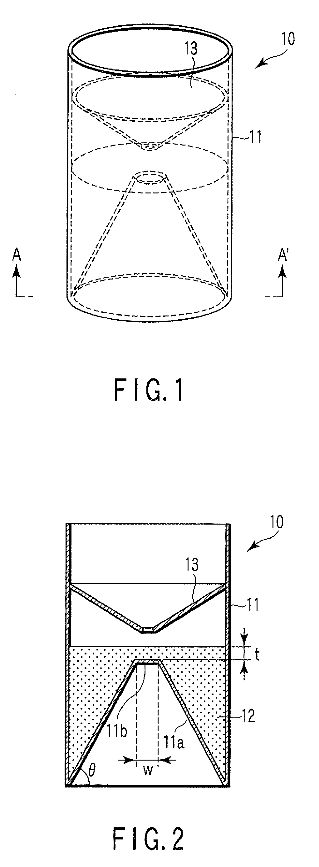
[0041]FIG. 1 is a perspective view illustrating a particle agglutination-evaluating container 10 according to the first embodiment of the present invention. FIG. 2 is a sectional view illustrating the particle agglutination-evaluating container 10 shown in FIG. 1, when cut along the line A-A′.

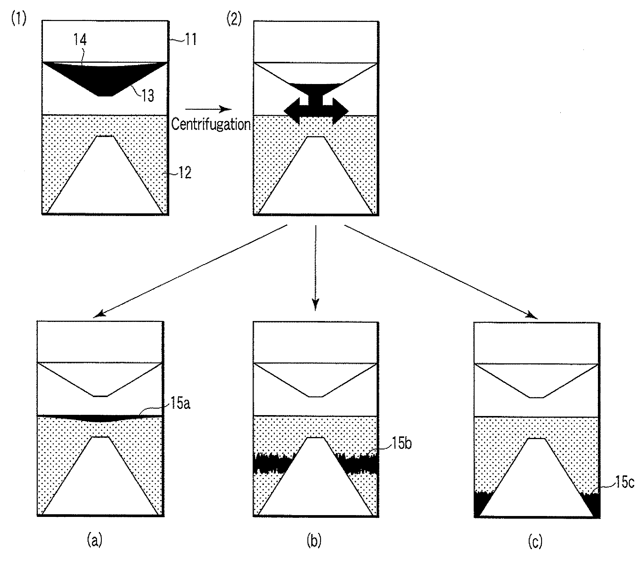
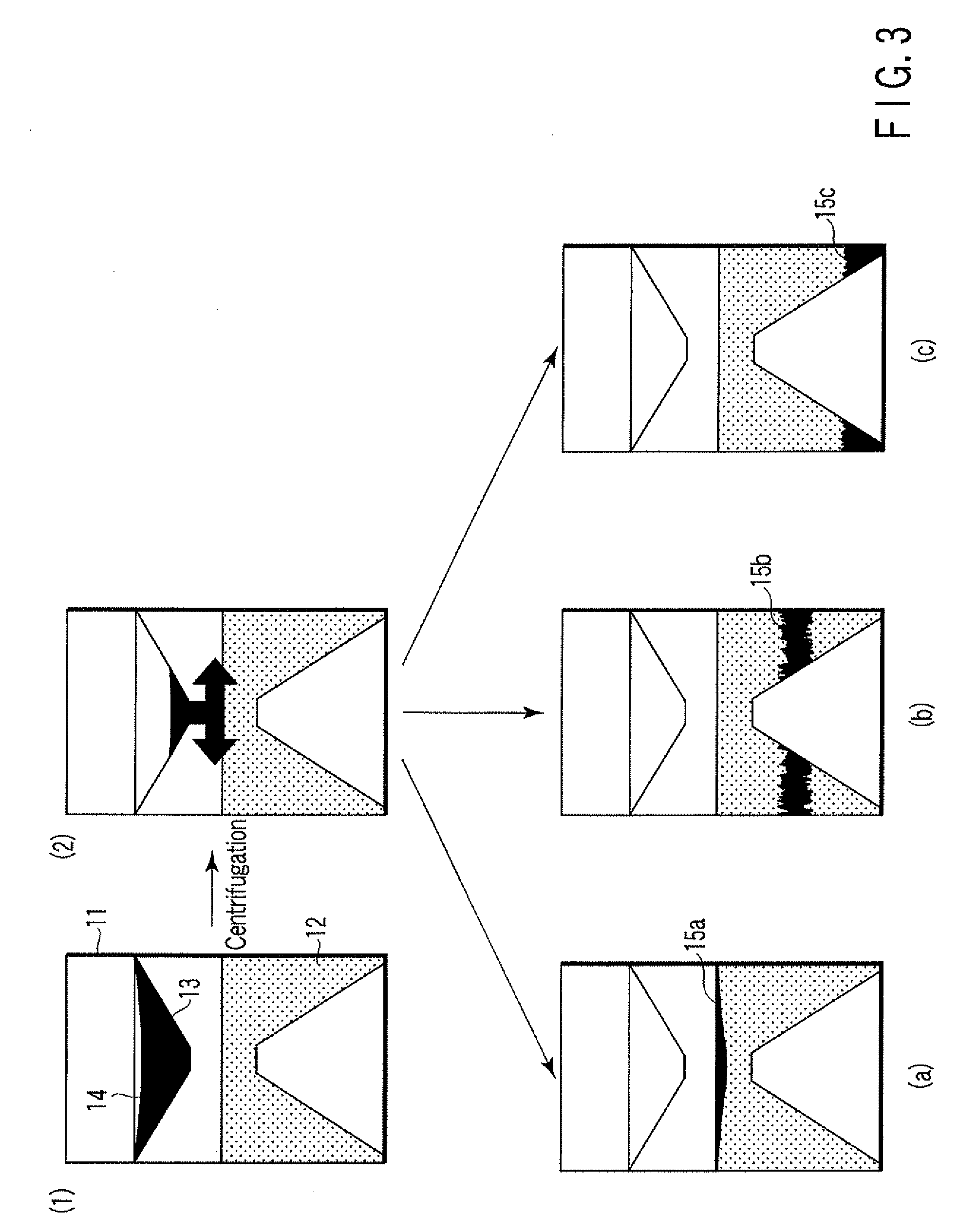
[0042]A transparent container main body 11 of the particle agglutination-evaluating container 10 is cylindrical in its external shape, and has a bottom face including a sloping bottom face 11a and a raised bottom face 11b extended horizontally at the top of the sloping bottom face 11a to form an obtuse angle with the sloping bottom face. The bottom face has an inverted-V shape of a truncated circular cone, and the raised bottom face 11b is a horizontal face. The transparent container main body 11 is filled with insoluble particles for separating agglutination particles depending on the degree of agglutination, forming therein a fluidal separation layer 12. The transparent container main body 11...

modified examples

[0063]Hereinafter, modified examples of the particle agglutination-evaluating container according to the first embodiment of the present invention will be described. In the modified examples, only the points different from the first embodiment of the present invention will be described.

[0064]A sectional view of a particle agglutination-evaluating container of modified example 1 is shown in FIG. 5 in which the flat raised bottom face in the first embodiment is replaced with a rounded raised bottom face. The rounded raised bottom face enables migration of negative unagglutinated particles toward the sloping bottom face without accumulation on the raised bottom face.

[0065]A sectional view of a particle agglutination-evaluating container of modified example 2 is shown in FIG. 6, in which the inverted-V shape of the truncated circular cone in the first embodiment is replaced with an inverted-U shape and the gradient angle of the sloping bottom face is changed to increase in the region cl...


PUM

PropertyMeasurementUnit
Thicknessaaaaaaaaaa
Angleaaaaaaaaaa
Angleaaaaaaaaaa

Abstract

A particle agglutination-evaluating container for immunological analysis, based on an agglutinate formed in an agglutination reaction between an antibody- or antigen-containing sample and agglutination particles, includes a transparent container body having a bottom face including a sloping bottom face and a raised bottom face extended in a horizontal direction at the top of the sloping bottom face to form an obtuse angle with the sloping bottom face, and a fluidal separation layer containing insoluble particles which are filled in the container body and where the agglutination particles are separated according to the agglutination degree, wherein agglutination is evaluated by observation from the bottom of the container body, where the agglutination reaction is judged positive when the agglutination particles are observed through the raised bottom face, negative when observed at the bottom end of the sloping bottom face, and weakly positive when observed in the middle of the sloping bottom face.

Description

CROSS REFERENCE TO RELATED APPLICATIONS[0001]This is a Continuation Application of PCT Application No. PCT / JP2007 / 061263, filed Jun. 4, 2007, which was published under PCT Article 21(2) in Japanese.[0002]This application is based upon and claims the benefit of priority from prior Japanese Patent Application No. 2006-156266, filed Jun. 5, 2006, the entire contents of which are incorporated herein by reference.BACKGROUND OF THE INVENTION[0003]1. Field of the Invention[0004]The present invention relates to a particle agglutination-evaluating container for use in evaluation of a particle agglutination pattern in an immunological agglutination reaction. In particular, the present invention relates to a particle agglutination-evaluating container for evaluation of various blood types or detection of an antigen or antibody, based on the agglutination pattern of blood cell particles.[0005]2. Description of the Related Art[0006]Conventionally, immunological agglutination reactions such as an...

Claims


Application Information

Patent Timeline
IPC IPC(8): B01J19/00
CPCB01L3/5082B01L2300/0654B01L2300/0851G01N2021/0378G01N33/537G01N2021/0325G01N21/03
Inventor TAMAI, TOYOHIRONARITA, HITOSHIKANEKO, YASUNOBUKOBAYASHI, YUMI
Owner BECKMAN COULTER INC
Why Eureka
Try Eureka