Injection Compression Moulding Apparatus

a technology of injection compression and moulding apparatus, which is applied in the field of injection compression moulding apparatus of plastics material, can solve the problems of large gap between the two parts of the mould, difficult formation of thin articles, and inability to form thin objects,

Inactive Publication Date: 2008-09-04
IM PAK TECH LTD
View PDF3 Cites 0 Cited by
  • Summary
  • Abstract
  • Description
  • Claims
  • Application Information

AI Technical Summary

Problems solved by technology

It is known that large, thin articles are difficult to form by injection moulding.
The reason is that the gap between the two parts of the mould is small and the distance that the material has to travel is too long for the pressure applicable by the moulding machine to be available at the far end of the gap from the injection point for driving the plastics to fill the mould.
Such techniques are limited in their application as they cannot produce articles of even wall thickness or articles that have regions of increased or reduced wall thickness.
Though injection moulding presses are capable of applying and maintaining the desired high pressure once the mould has been closed, their speed of movement just before the mould is fully closed, is not necessarily optimum.
For thinner sections, the speed may be too low and, for thicker sections, the speed may be too high and uncontrollable.

Method used


Image

  • Injection Compression Moulding Apparatus
  • Injection Compression Moulding Apparatus
  • Injection Compression Moulding Apparatus

Examples


Embodiment Construction

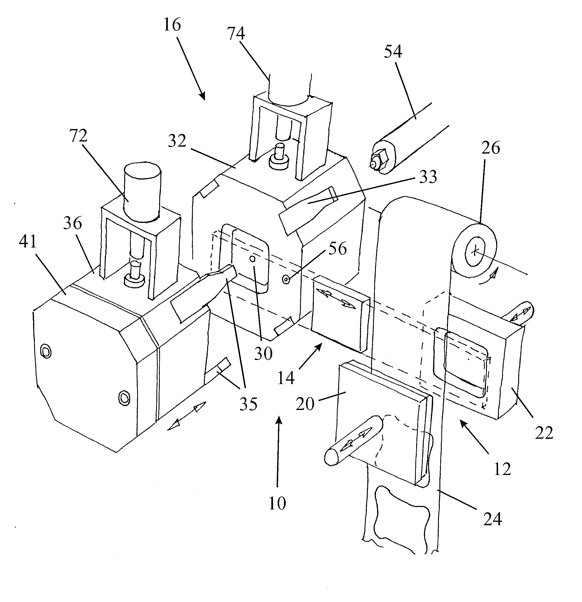
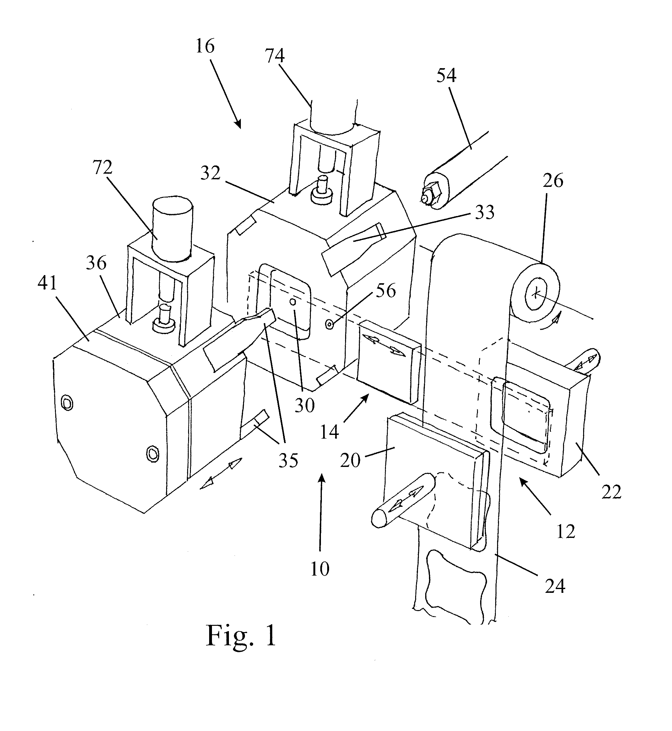
[0018]FIG. 1 shows schematically an apparatus 10 for forming a square container of the type commonly used, for example, in packaging margarine. Currently, such containers are often formed by thermoforming. In this process, a flat sheet is stretched by means of an applied vacuum and optional mechanical assistance to conform to a female mould. The process has disadvantages in that the base of the formed container is thicker than it needs to be, while the sides and the corner are weakened unnecessarily. In other words, the best use is not made of the plastics material. Furthermore, the plastics material does not contain an oxygen barrier and this reduces the shelf life of the packaged comestible product.

[0019]Conventional injection moulding can alternatively be used to form such an article but the length to thickness ratios are such that expensive material have to be used. Even when using low viscosity plastics materials, one is obliged to make the sides of the container thicker than n...


PUM

PropertyMeasurementUnit
thicknessaaaaaaaaaa
speedaaaaaaaaaa
speedsaaaaaaaaaa

Abstract

An injection compression moulding apparatus comprises two mould parts which define a mould cavity and are mounted on two relatively movable platens of an injection moulding press. An actuator is arranged in series with the platen action on at least one of the mould parts and is controlled in synchronism with the movement of the platens to enable the relative speed of the two mould parts during a mould closing phase of each article moulding cycle to be modified, the speed of relative movement of the mould parts being the vector sum of the speeds of movement and the platens and the actuator.

Description

FIELD OF THE INVENTION[0001]The present invention relates to apparatus for injection compression moulding of plastics material.BACKGROUND OF THE INVENTION[0002]It is known that large, thin articles are difficult to form by injection moulding. The reason is that the gap between the two parts of the mould is small and the distance that the material has to travel is too long for the pressure applicable by the moulding machine to be available at the far end of the gap from the injection point for driving the plastics to fill the mould. In short, the “flow path thickness ratio” is too long.[0003]Conventionally, thin articles are formed by vacuum or pressure forming where a sheet of plastics material is stretched to conform to the shape of a mould. Such techniques are limited in their application as they cannot produce articles of even wall thickness or articles that have regions of increased or reduced wall thickness. This is because only one surface of the article is being moulded and t...

Claims


Application Information

Patent Timeline
Patent Type & Authority Applications(United States)
IPC IPC(8): B29C45/56B29C45/67B29C45/16
CPCB29C45/1671B29C45/561B29C2045/564B29C2045/563B29C2045/14942
Inventor CLARKE, PETER
Owner IM PAK TECH LTD
Why Eureka
Try Eureka