
Security gate

a technology for security gates and gates, applied in the field of security gates, can solve the problems of preventing the installation of gates in a variety of applications, and achieve the effects of simplifying the form of the housing spanning, reducing the cost of installation, and simplifying the construction

Inactive Publication Date: 2008-09-11
LETKEMAN JORDAN +3
View PDF17 Cites 19 Cited by
  • Summary
  • Abstract
  • Description
  • Claims
  • Application Information

AI Technical Summary

Benefits of technology

[0011]By providing a drive linkage which can be coupled directly to the first panel adjacent the posts, a simpler and lower cost construction results which does not require an elaborate housing for coupling the drive linkage to the free ends of the second panels. Coupling of the drive linkage directly to the first panel adjacent the inner end thereof can be accomplished by use of the guide mechanism coupled to the second panel. When driving the first panel directly, the guide mechanism may take the form of a simple surface mounted track below the gate, or in other embodiments an auxiliary link coupled between the post and the second panel. By simplifying the form of the housing spanning between the two posts, the gate can be installed more simply and in more varied locations.

Problems solved by technology

In either instance considerable limitations prevent installation of the gate in a variety of applications due to the limited height requirements for the overhead enclosures or the complex and costly installation requirements for below ground drive linkages.

Method used


Image

  • Security gate
  • Security gate
  • Security gate

Examples


Embodiment Construction

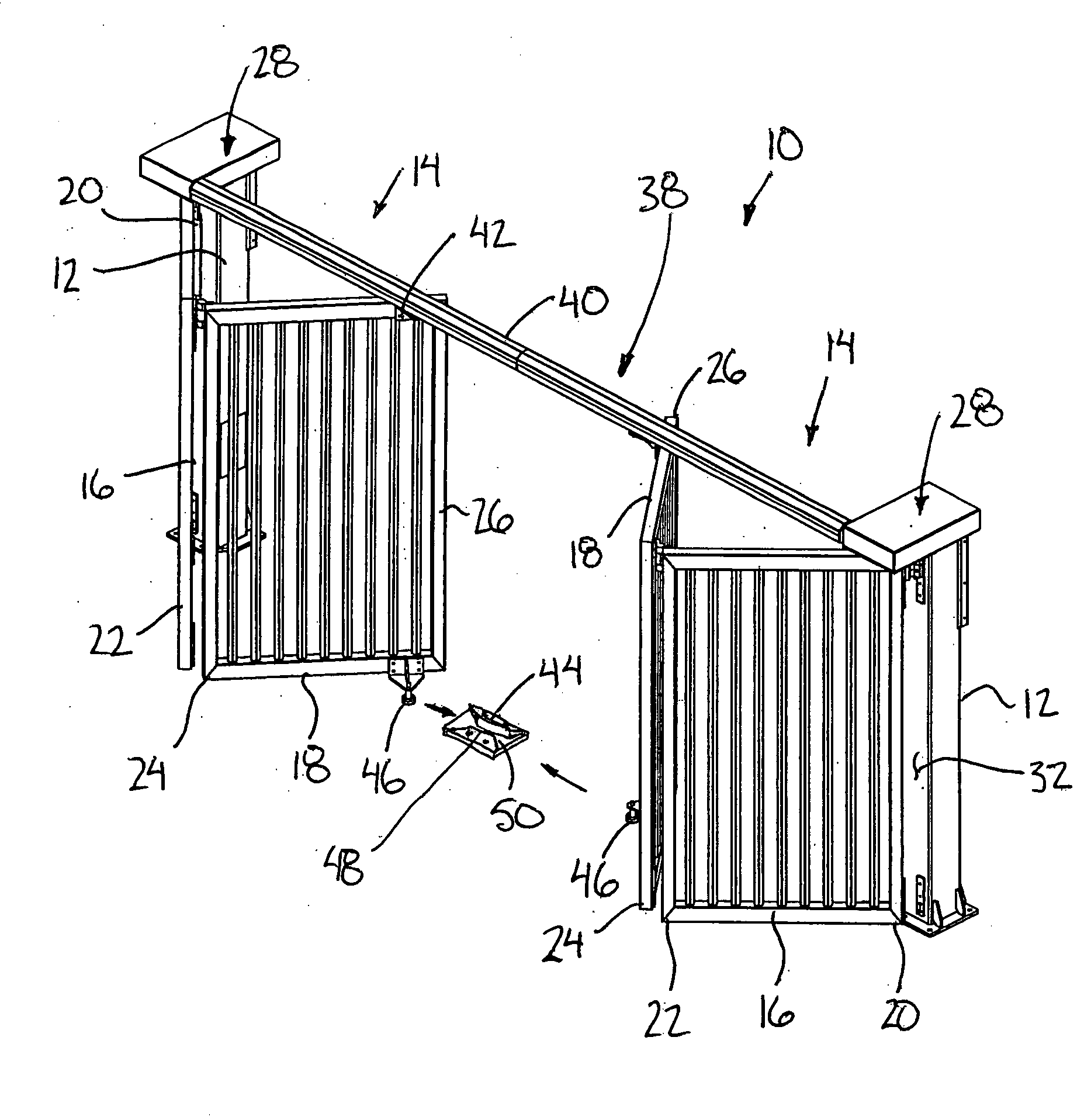
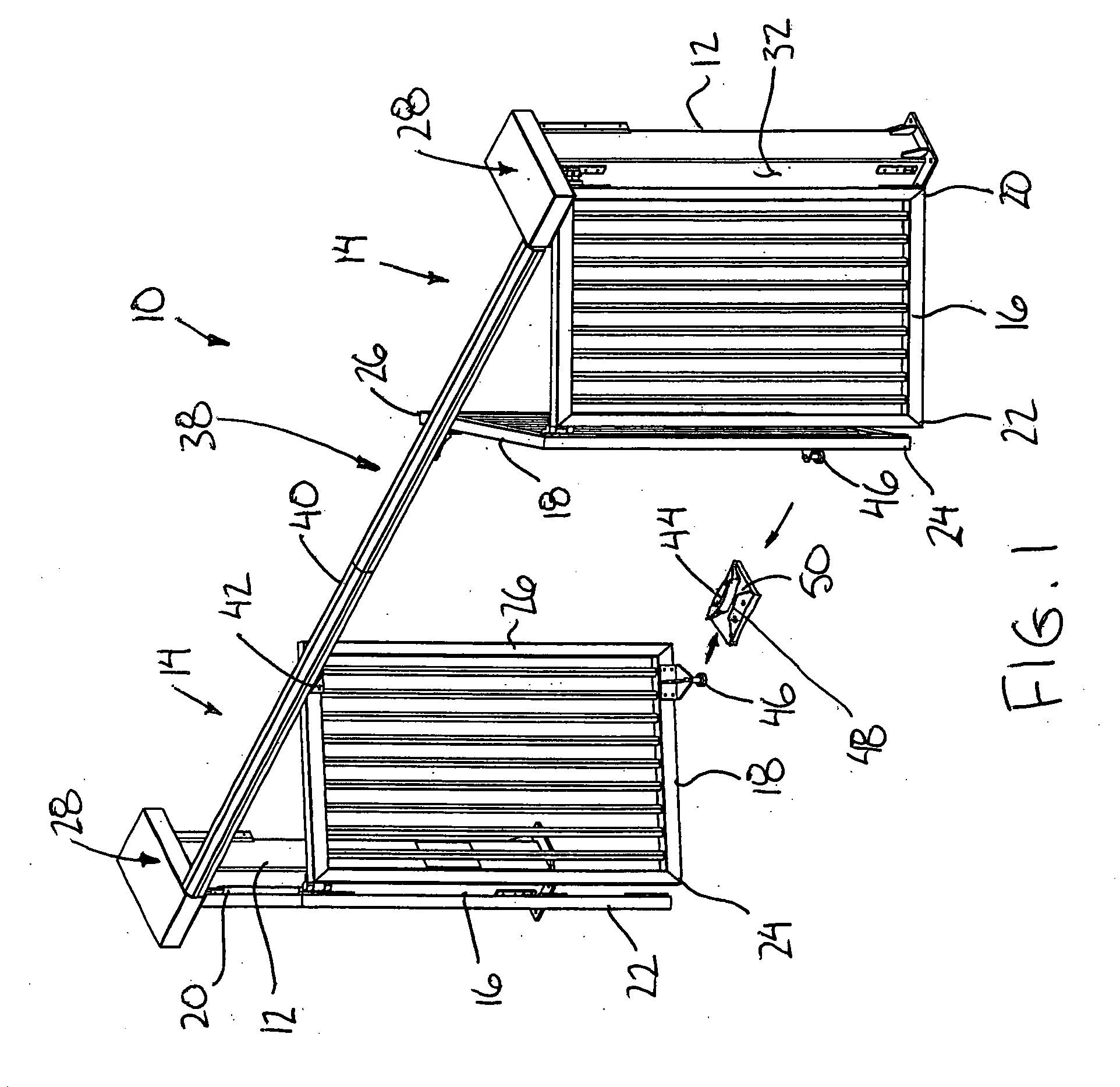
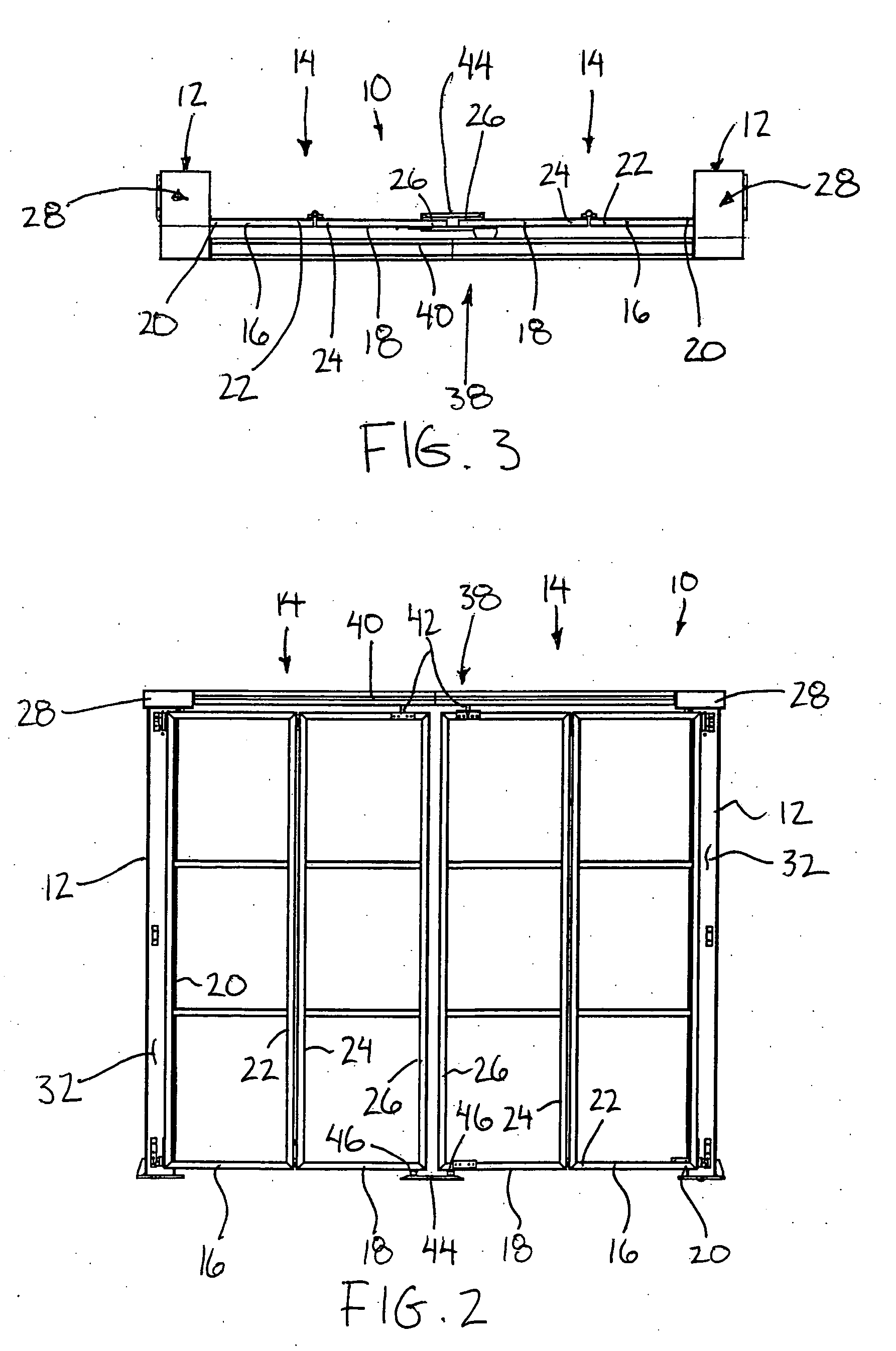
[0038]Referring to the accompanying figures there is illustrated a security gate generally indicated by reference numeral 10. The security gate 10 is particularly suited for selectively spanning a gate opening across a roadway and the like. Although various embodiments of the gate are shown in the accompanying illustrations, the common features of each will first be described herein.

[0039]The security gate 10 includes a pair of posts 12 which are fixed mounted in the ground in an upright orientation at opposing sides of the gate opening spanning therebetween. A pair of gate members 14 are pivotally supported on the posts 12 respectively. Each gate member includes a first panel 16 and a second panel 18 comprised of a rigid rectangular frame including perimeter frame members and crossbars spanning there across.

[0040]The first panel spans between an inner end 20 pivotally supported on the post 12 for relative pivotal movement about a first vertical axis to an outer end 22. The second p...


PUM


Abstract

A security gate comprises a pair of posts fixed adjacent opposing sides of a gate opening. The gate includes a pair of first gate panels pivotally mounted on the posts and second gate panels pivotally coupled to the outer ends of the first gate panels respectively so that the second gate panels meet one another in the closed position of the gate. Each first gate panel and the respective second gate panel pivotally coupled thereto are moveable together between an open position folded adjacent the respective post and a closed position spanning across the gate opening. A drive linkage is coupled between each post and the inner end of the respective first gate panel pivotally coupled thereto to drive pivotal movement of the first gate panel between the open and closed position. A guide mechanism is coupled between the fixed post and the inner end of the second gate panel for guiding pivotal movement of the second gate panel between the open and closed positions responsive to movement of the first gate panel.

Description

[0001]This application claims the benefit under 35 U.S.C. 119(e) of U.S. provisional application Ser. No. 60 / 789,134, filed Apr. 5, 2006.FIELD OF THE INVENTION[0002]The present invention relates to a security gate for selectively spanning a gate opening and more particularly relates to a security gate comprising a pair of hinged gate panels driven by a linkage between open and closed positions.BACKGROUND[0003]A common structure of a security gate includes an upright post fixedly supported on both sides of a gate opening across which the gate is to span. Each post mounts a gate member thereon comprising a pair of hinged panels which are foldable relative to the post between a closed position in which the free ends of the gate members meet at the center of the gate opening and the panels span the opening, and an open position in which the panels are folded so that the free ends of the gate members are positioned adjacent the posts respectively. Known security gate designs require a dr...

Claims


Application Information

Patent Timeline
IPC IPC(8): E05F15/14E05F15/06E05F15/56
CPCE05D15/264E05Y2201/646E05Y2201/656E05F15/63E05Y2900/132E05Y2900/40E05F15/605E05Y2600/10
Inventor LETKEMAN, JORDANBUHLER, LARRYBUHLER, JAMESKEHLER, SHANNON
Owner LETKEMAN JORDAN
Learn More