

Dry Ice Blasting With Ozone-Containing Carrier Gas
a carrier gas and dry ice blasting technology, applied in the field of dry ice blasting with ozone-containing carrier gas, can solve the problems of shrinkage and loose adhesion of contaminants on the target material surface to the target material, and the potential application and/or the effectiveness of a given application,
- Summary
- Abstract
- Description
- Claims
- Application Information
AI Technical Summary
Problems solved by technology
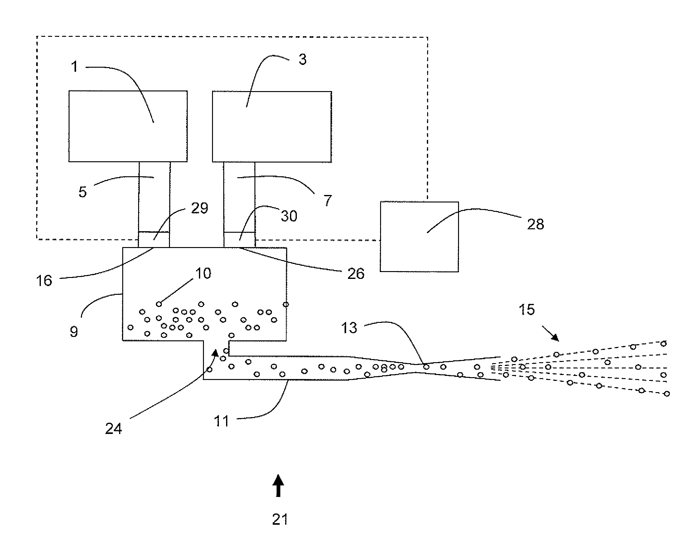
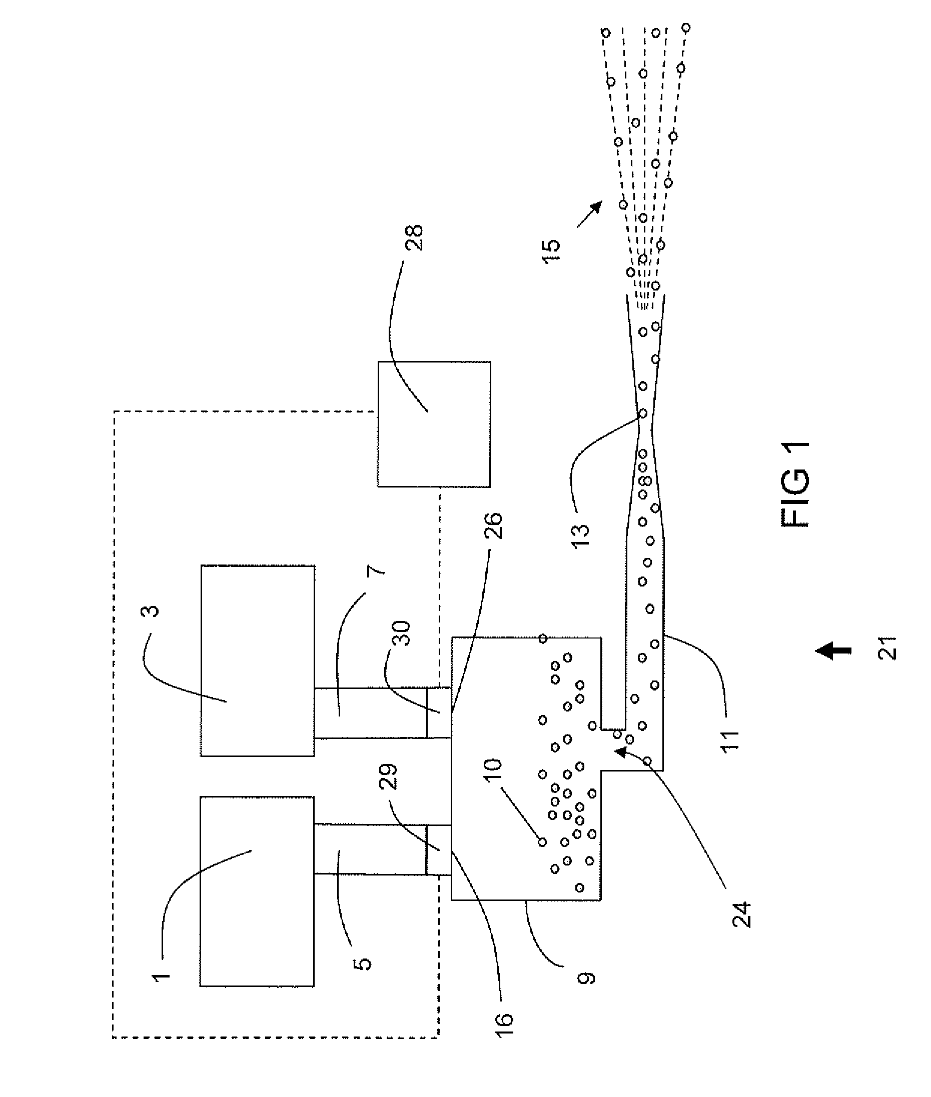
Method used
Image

Examples
Embodiment Construction
[0051]The words and phrases used herein should be given their ordinary and customary meaning in the art by one skilled in the art unless otherwise further defined.
[0052]In the following, reference is made to embodiments of the invention. However, it should be understood that the invention is not limited to specific described embodiments. Instead, any combination of the following features and elements, whether related to different embodiments or not, is contemplated to implement and practice the invention. Furthermore, in various embodiments the invention provides numerous advantages over the prior art. However, although embodiments of the invention may achieve advantages over other possible solutions and / or over the prior art, whether or not a particular advantage is achieved by a given embodiment is not limiting of the invention. Thus, the following aspects, features, embodiments and advantages are merely illustrative and are not considered elements or limitations of the appended c...
PUM
| Property | Measurement | Unit |
|---|---|---|
| temperature | aaaaa | aaaaa |
| sizes | aaaaa | aaaaa |
| pressure | aaaaa | aaaaa |
Abstract
Description
Claims
Application Information