Container

US20080217190A1Active Publication Date: 2008-09-11TOKUYAMA DENTAL CORP

Image

  • Container
  • Container
  • Container

Examples


second embodiment

[0059]Next, described below is the present invention.

[0060]The same portions as those of the above first embodiment are denoted by the same reference numerals but their detailed description is not repeated.

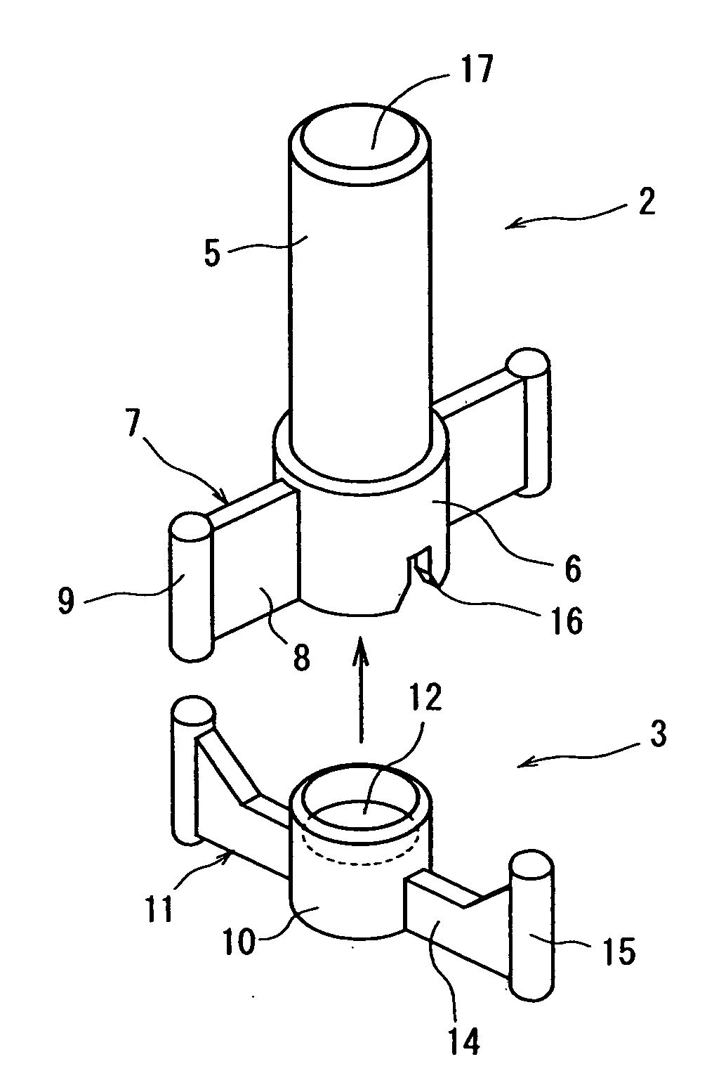
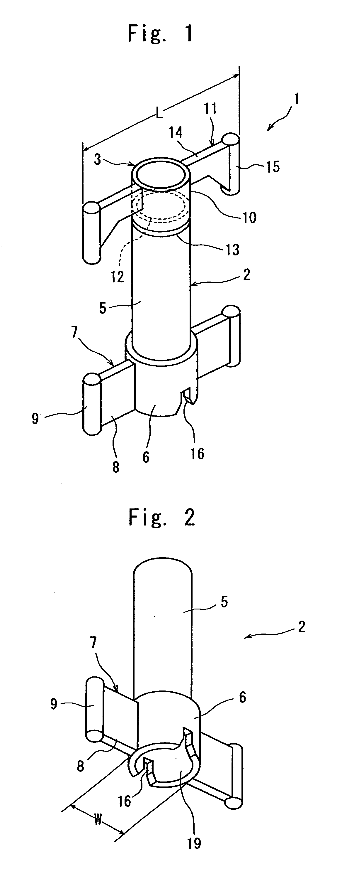
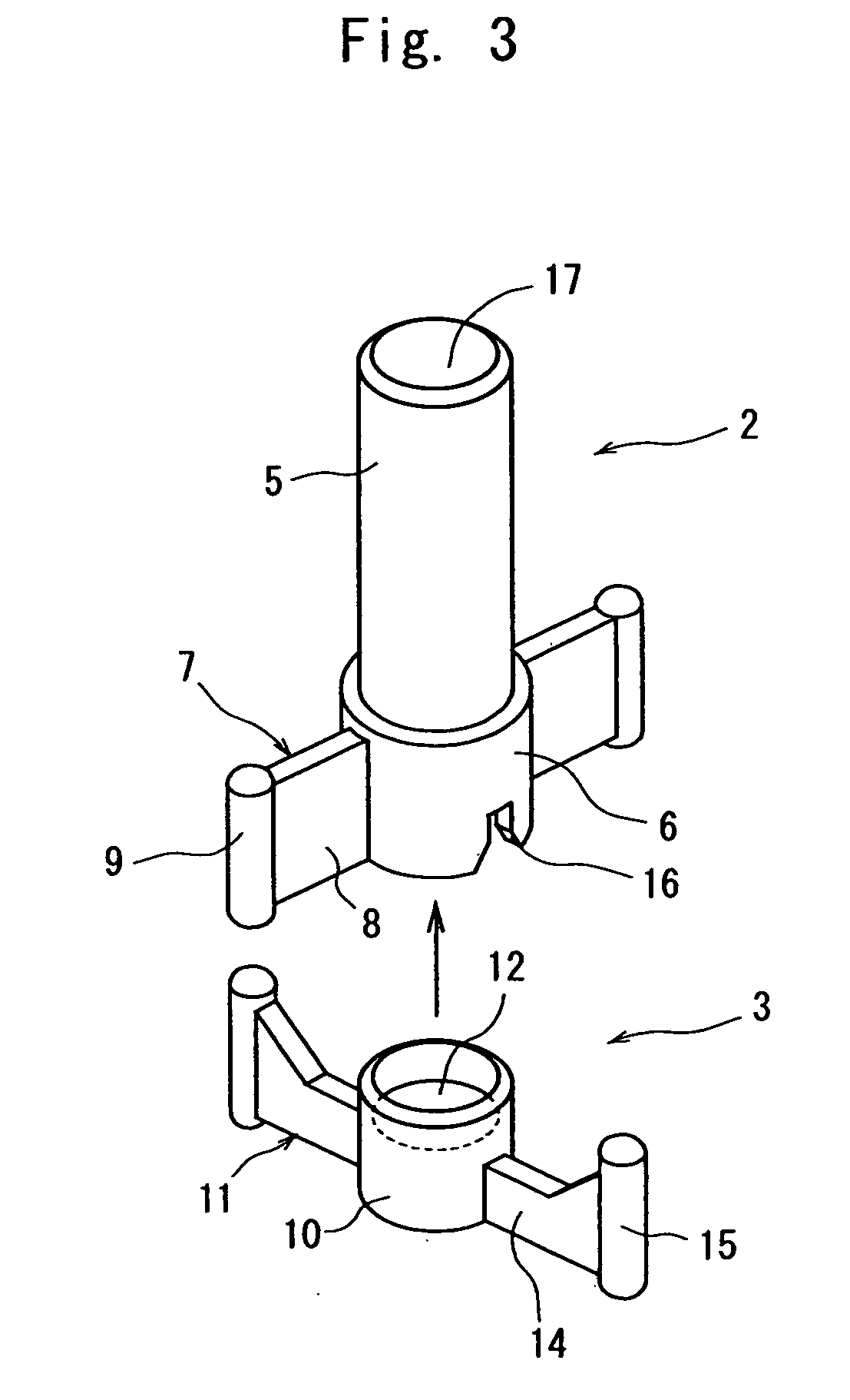
[0061]In the above first embodiment as shown in FIG. 1, two auxiliary leg portions 7 are formed on the side of the container body 2, and the holding leg portions 11, too, are similarly formed in a number of two on the lid member 3. However, the numbers of the auxiliary leg portions 7 and holding leg portions 11 may be suitably varied.

[0062]FIG. 5 is a sectional view of the pedestal portion 6 of the container body 2. In this embodiment, four auxiliary leg portions 7 are formed on the outer circumferential portion of the pedestal 6. Two sets of auxiliary leg portions 7 are arranged being opposed to each other in the direction of diameter of the pedestal 6, each set of auxiliary leg portions 7 being close to each other. Here, a maximum distance M at the distal ends of each set of aux...


PUM


Abstract

A container which is not bulky at the time of shipping and can be stably stood on a suitable place. The container includes a lid member for closing a take-out opening (brittle portion) of the container body 2. On the lower outer side of the container body, there are formed slits for fitting the lid member to the container body after the container body and the lid member are separated apart, and auxiliary leg portions that protrude outward of the container body. The lid member is forming holding leg portions that protrude outward therefrom. Wing portions of the holding leg portions are inserted in the slits to fit the lid member to the container body, and the erected attitude of the container body is supported by the holding leg portions.

Description

BACKGROUND OF THE INVENTION[0001]1. Field of the Invention[0002]The present invention relates to a container in which the junction between an opening portion of a container body and a lid member is accomplished relying on a brittle portion, and the container body and the lid member can be separated away from each other by breaking the junction which is the brittle portion, the container capable of maintaining an erected attitude by using the lid member even if the container has such a shape which by itself cannot maintain the erected attitude.[0003]2. Description of the Related Art[0004]Adhesives for dental use can be grouped into those that are contained in a container designed for repetitive use a plurality of number of times and those that are contained in a container designed for use for the therapy of only one time. The former container designed for repetitive use a plurality of number of times contains the adhesive in an amount to meet the therapy of a plurality of number of t...

Claims


Application Information

Patent Timeline
11 Sep 2008
Publication
US20080217190A1
IPC
A61C19/02; A61J1/00; B65D17/32; A61C5/66
CPC
A61C5/066; A61C2202/01; A61C2202/00; A61C5/66
Inventors
MATSUSHIGE, KOJI; AIZAWA, MASAYUKI