Cooling fan and method of fabrication

a cooling fan and fabrication method technology, applied in the field of cooling fans, can solve the problems of instability of bearings, easy wear of the inner circumferential periphery of the frame, and unbalanced rotation of the cooling fan rotor

Inactive Publication Date: 2008-09-11
HON HAI PRECISION IND CO LTD
View PDF9 Cites 32 Cited by
  • Summary
  • Abstract
  • Description
  • Claims
  • Application Information

AI Technical Summary

Benefits of technology

[0008]The present invention relates, in another aspect, to a method for making the cooling fan. The method includes steps of: a) providing a bearing; b) mounting the bearing in a mold used for making a fan housing; c) molding the fan housing using injection molding, a central tube being formed fixedly connected to the bearing and around the bearing during the process of molding the fan housing; d) mounting a stator around the central tube; e) mounting a rotor to the bearing.

Problems solved by technology

However, as the frame is generally made of plastic, when the bearing is placed into the central tube, an inner circumferential periphery of the frame may easily wear out.
Thus a clearance may be formed between the bearing and the central tube when the bearing is assembled with the central tube of the frame to form the cooling fan, which, in most of cases, results in instability of the bearing and unbalanced rotation of the rotor of the cooling fan.
Thus not only assembly of the bearing is inconvenience, but also results in noise or malfunctioning of the cooling fan.
The performance of the cooling fan is reduced, and the life-span is resultingly shortened.

Method used


Image

  • Cooling fan and method of fabrication
  • Cooling fan and method of fabrication
  • Cooling fan and method of fabrication

Examples


Embodiment Construction

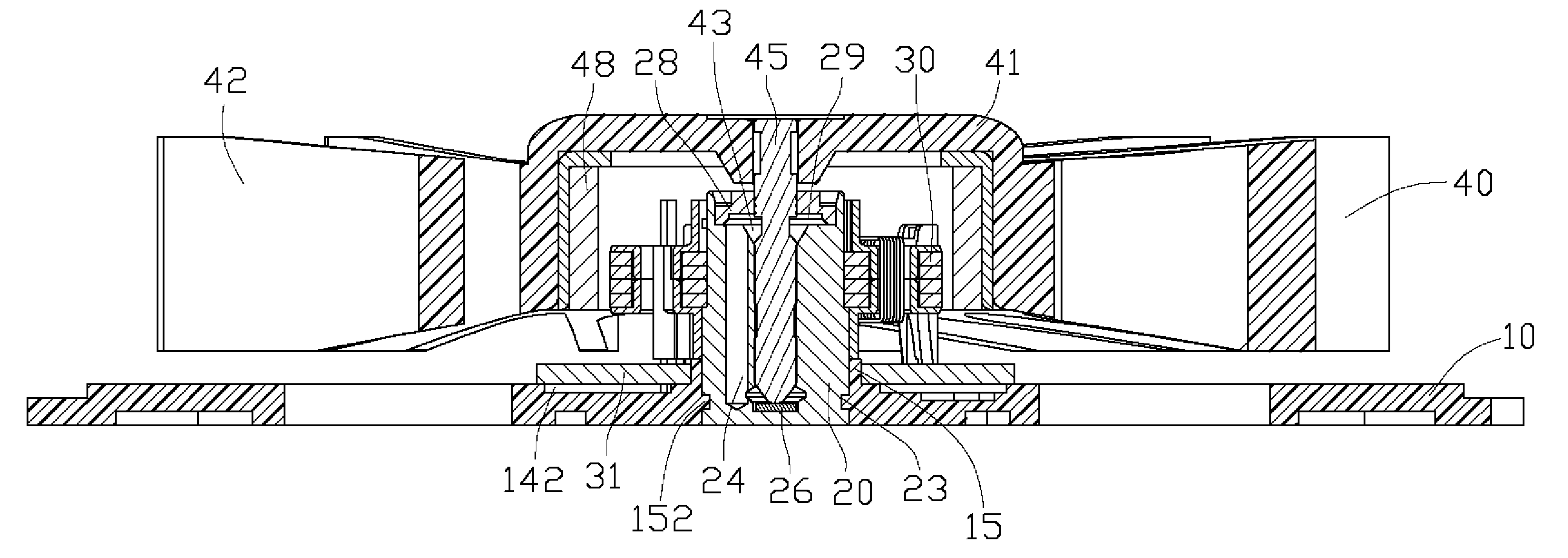
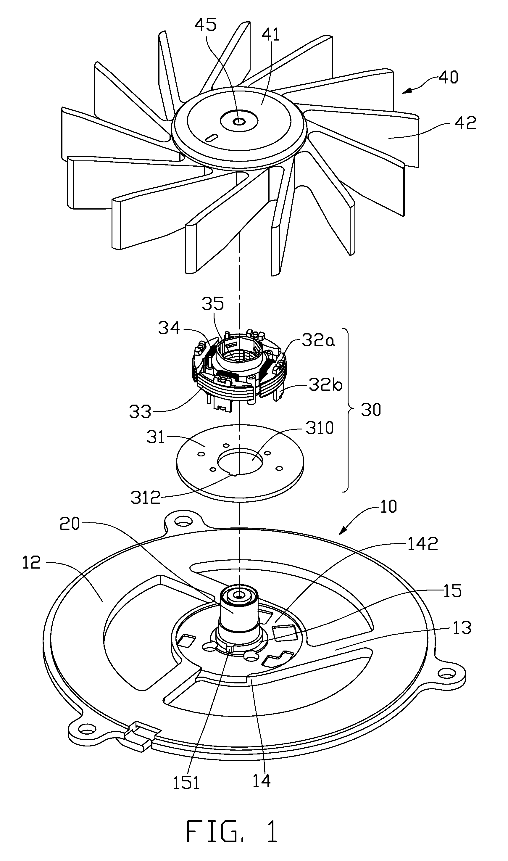
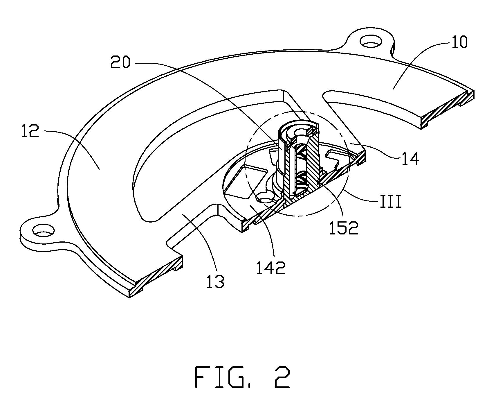
[0021]Referring to FIGS. 1-3, a cooling fan according to a preferred embodiment of the present invention includes a fan housing 10, a bearing 20 mounted in the housing 10, a stator 30 mounted around the bearing 20, and a rotor 40 being rotatablely supported by the bearing 20.

[0022]The housing 10 includes a ring shaped main body 12 defining an aperture (not labeled) in a central portion thereof, a base 14 being formed in the aperture of the housing 10, and a plurality of ribs 13 interconnecting an outer periphery of the base 14 and an inner periphery of the main body 12. The base 14 defines a concave 142 in a central portion thereof. A central tube 15 extends upwardly from the base 14 from a central area of the concave 142. An ear 151 extends radially and outwardly from an outer surface of the central tube 15. The ear 151 has a shape of square column which has a square shaped cross section. Alternatively, the ear 151 can be a semicircular column with a semicircular shaped cross secti...


PUM


Abstract

A cooling fan includes a fan housing (10) having a central tube (15) extending upwardly therefrom, a bearing (20) defining a bearing hole (22) therein, a stator (30) mounted on the central tube, and a rotor (40) including a hub (12) having a shaft (18) extending from the hub into the bearing hole of the bearing. The bearing is received and fixedly connected to the central tube during the plastic injection molding of the fan housing; thus the bearing and the central tube are integrally connected together. The bearing can be precisely and firmly secured to the central tube of the fan housing.

Description

BACKGROUND OF THE INVENTION[0001]1. Field of the Invention[0002]The present invention relates to a cooling fan, and more particularly relates to a cooling fan which can be assembled easily. The present invention relates also to a method for making the cooling fan.[0003]2. Description of Related Art[0004]With the continuing development of the electronic technology, electronic packages such as CPUs (central processing units) are generating more and more heat that requires immediate dissipation. Cooling fans are commonly used in combination with heat sinks for cooling CPUs.[0005]A conventional cooling fan includes a rotor having a shaft extending downwardly from a central portion of the rotor, a bearing defining an inner hole for receiving the shaft therein, and a frame. A central tube extends upwardly from a middle portion of the frame and defines a through hole therein. The bearing is mounted in the through hole of the central tube of the frame. To avoid swinging of the bearing, the ...

Claims


Application Information

Patent Timeline
Patent Type & Authority Applications(United States)
IPC IPC(8): H02K7/00H02K5/16F04B17/00
CPCF04D29/646H02K1/187H02K5/1675F04D25/0626F04D25/062
Inventor ZHANG, QIANGSHIH, WUN-CHANGHUANG, RUI-JUN
Owner HON HAI PRECISION IND CO LTD
Why Eureka
Try Eureka