System and method for improving infrared detector performance in dual detector system

a dual detector and infrared technology, applied in the field of motion detectors, can solve the problems of pir motion detectors being susceptible to false alarms, exacerbated by the problem, insects crawling on the detector cover or flying very near the detector, etc., to improve false alarm immunity, minimize false alarms, and reduce pir sensitivity

Active Publication Date: 2008-09-11
ROBERT BOSCH CORP +1
View PDF25 Cites 13 Cited by
  • Summary
  • Abstract
  • Description
  • Claims
  • Application Information

AI Technical Summary

Benefits of technology

[0011]In one aspect, a method for minimizing false alarms due to small animals and insects in a coverage area of a dual detector system is provided. The dual detector system includes at least one MW sensor and at least one PIR sensor. The method may include determining a target range for a detected target based on received MW signals. The method may additionally include adjusting a PIR sensor threshold based on the determined target range. The PIR sensor threshold is adjusted to a first level when the detected target is a short range target and second level when the target is a longer range target, such that the first level is higher than the second level. If for any reason, PIR sensitivity is reduced at close range, perhaps due to multiple PIR signals with different circuit gains, or due to mirror or lens performance, the first level may be lower than the second level. In addition to PIR sensor threshold, PIR sensitivity may be adjusted by changing the duration, quantity, or frequency of pulses required to cause an alarm. Other configurations involving more than two alarm sensitivities are

Problems solved by technology

PIR motion detectors are susceptible to false alarms caused by small animals close to the detector.
In cold environments, the greater differential between small animal infrared emissions and that of the background can exacerbate this problem.
Insects crawling on a detector cover or flyin

Method used


Image

  • System and method for improving infrared detector performance in dual detector system
  • System and method for improving infrared detector performance in dual detector system
  • System and method for improving infrared detector performance in dual detector system

Examples


Embodiment Construction

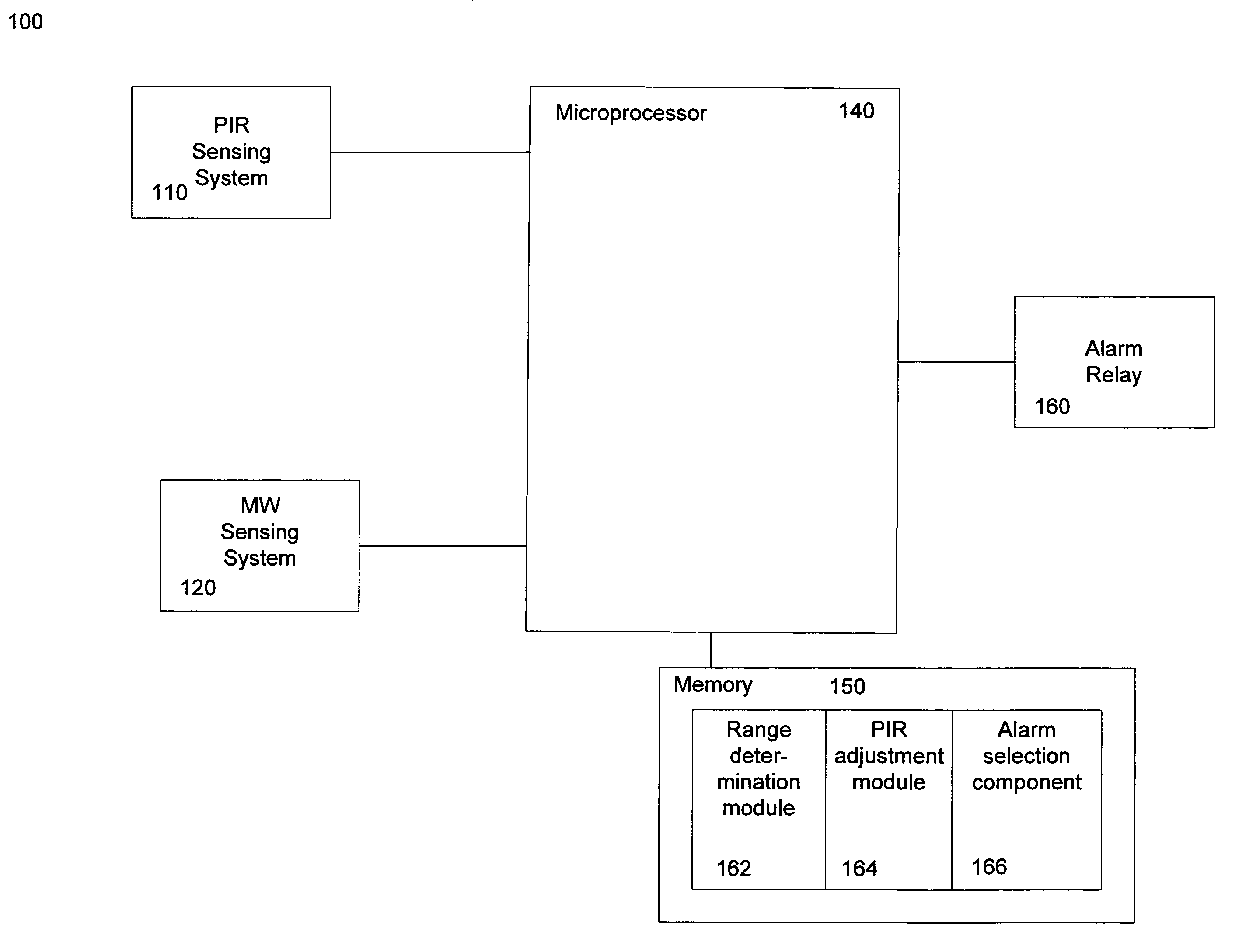
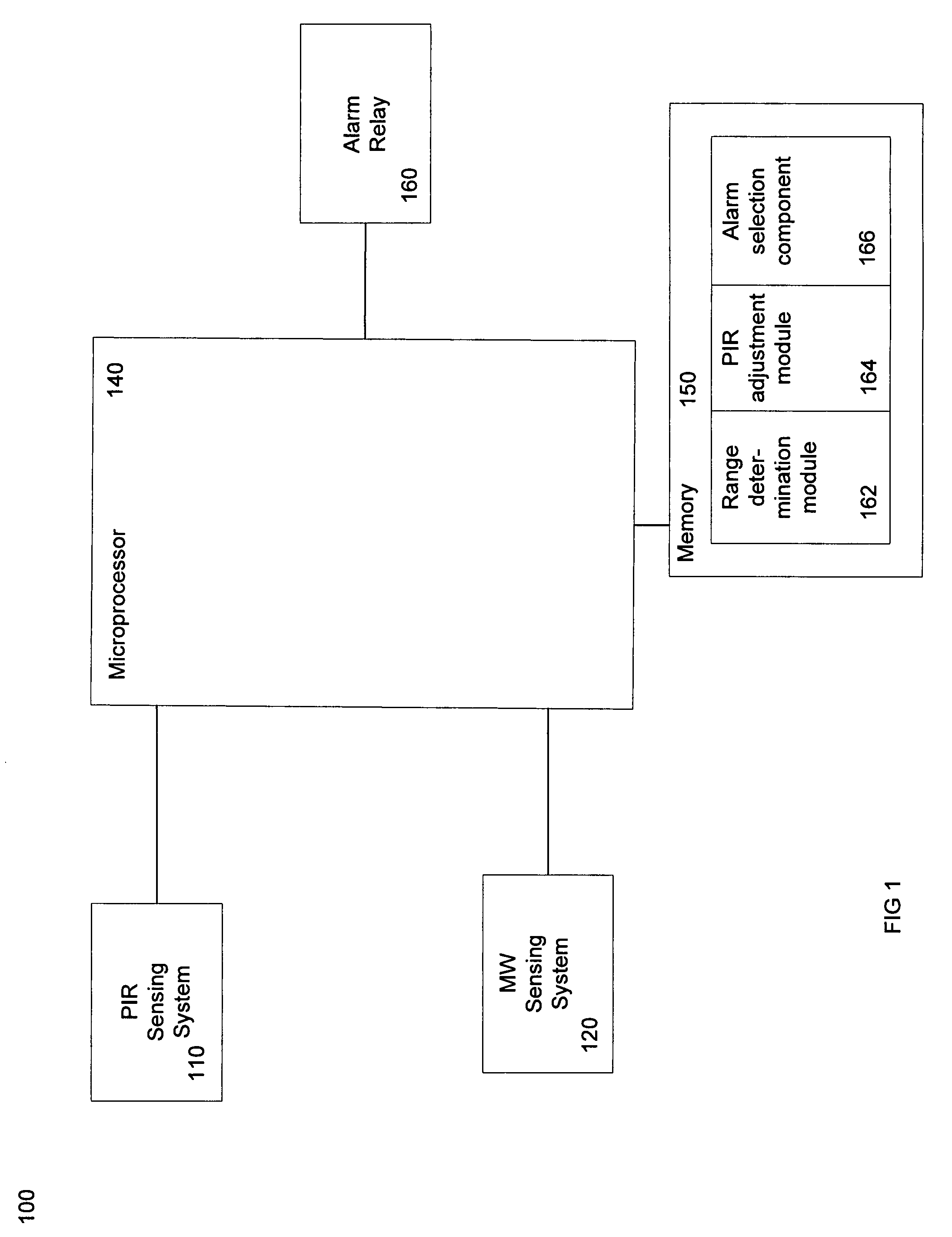
[0025]Embodiments of the present invention are directed to a system and method for adjusting PIR sensitivity in order to minimize false alarms in a dual detector system.

[0026]Potential false alarm sources to be addressed include small animals and insects, especially those near the detector. IR energy from small animals at close range may be comparable to IR energy emitted by humans at greater distances. Insects crawling on the detector cover may also be a source of false alarms if a heat source exists in the background. While the insect is cold blooded, having a body temperature equal to the ambient temperature, its body can shield the PIR sensor from a background heat source.

[0027]Embodiments of the invention are also directed to correcting detection limitations that are often present in dual detectors. For instance, intruders crawling beneath or in the near vicinity of the detector may produce low level signals, particularly if the detector is mounted high on a wall, or lenses or ...


PUM


Abstract

Embodiments of the present invention is directed to a method and system for use of ranging MW to reduce dual (MW/PIR) intrusion detector false alarms. A Doppler microwave system may be provided that is capable of detecting an object range and adjusting the sensitivity of the PIR detector to account for object size and range. Multiple range limited MW stages may be configured for different ranges to determine the general range of the moving object. Based on signal levels present on these MW stages, an approximate object range is determined. The sensitivity of the PIR is then adjusted based on a PIR sensitivity vs. object range function that is optimized to alarm on humans and ignore small animals and insects.

Description

TECHNICAL FIELD[0001]Embodiments of the present invention relate to motion detectors. More particularly, embodiments of the invention are directed to reducing the occurrence of false alarms and improving the performance of infrared detectors in dual detector systems.BACKGROUND OF THE INVENTION[0002]Currently, in the field of security systems, motion detectors are generally provided to detect intruders. Dual technology motion detectors incorporate multiple sensing technologies in order to provide efficient intruder detection with minimized risk of false alarms. Many dual detectors incorporate passive infrared (PIR) technology and microwave (MW) technology.[0003]PIR technology has long been used in motion detectors. The PIR sensor detects the difference between the infrared energy emitted from an intruder and that emitted from the ambient environment. Many PIR detectors utilize Fresnel lenses or custom shaped mirrors to focus infrared energy on a pyrodetector. The output signal from t...

Claims


Application Information

Patent Timeline
IPC IPC(8): G08B13/18
CPCG01S13/56G01S13/86G08B29/20G08B13/2494G08B29/183G01S13/886
Inventor ROYER, GREGORY
Owner ROBERT BOSCH CORP
Why Eureka
Try Eureka