Image display apparatus

a display apparatus and display technology, applied in the field of organic el display apparatus, can solve the problems of increasing data write time, inability to accurately display, and affecting the accuracy of gradation, so as to achieve the effect of preventing even luminan

Active Publication Date: 2008-09-11
SAMSUNG DISPLAY CO LTD +1
View PDF11 Cites 24 Cited by
  • Summary
  • Abstract
  • Description
  • Claims
  • Application Information

AI Technical Summary

Benefits of technology

[0041](17) The image display apparatus according to the item (13), wherein the field effect transistor and the switch means are disposed on a transparent substrate with the use of a polysilicon TFT (thin film transistor).
[0042]According to the present invention, even in the case of the standard mode, a period of time of the reset operation for resetting the gate voltage of the OLED drive TFT can be reduced. At the same time, the uneven luminance can be prevented in the case of the high luminance mode. Also, a period of time that has been saved by shortening the reset time is used, for example, in the characteristic inspection of the respective OLED elements, which can be effective to the feedback of the luminance adjustment.

Problems solved by technology

If not, Vth of the OLED drive TFT 3 cannot be sufficiently compensated, and the precise gradation display cannot be conducted.
In particular, in the first conventional example, when the reset time is large, the data write time is increased, and a period of time during which the OLED element 1 emits a light to form an image is limited.
In this case, there arises such a problem that it is impossible to measure the emission characteristic of the respective OLED elements 1 by the use of the blanking period.

Method used


Image

  • Image display apparatus
  • Image display apparatus
  • Image display apparatus

Examples


first embodiment

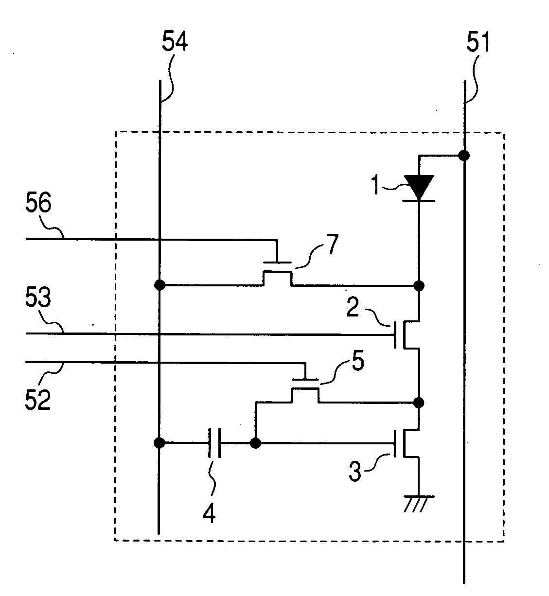
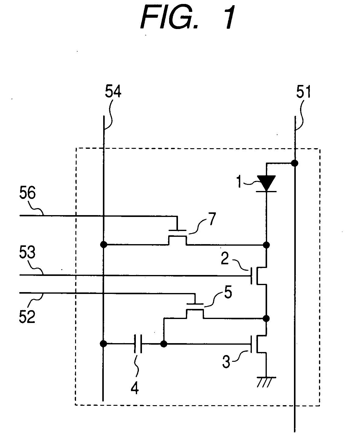
[0064]FIG. 1 is a circuit diagram showing a pixel structure according to the present invention. The circuit shown in FIG. 1 according to the present invention copes with the problems with the first conventional example of the prior art. The basic operation of FIG. 1 is identical with that in the first conventional example. That is, referring to FIG. 1, an OLED element 1, a lighting TFT switch 2, and an OLED drive TFT 3 are connected in series between a power supply line 51 and a reference potential. Referring to FIG. 1, the lighting TFT switch 2 is a switch that determines whether a current is allowed to flow in the OLED element 1, or not, and an OLED drive TFT 3 controls a current that flows in the OLED element 1 to determine the gradation of light emission of the OLED element 1. Image data is written in a retention volume 4 from a signal line 54.

[0065]Also, the reset operation is also identical with that in the first conventional example. That is, as described in the first convent...

second embodiment

[0083]FIG. 6 is a circuit diagram showing a pixel structure according to a second embodiment of the present invention. Referring to FIG. 6, the OLED drive TFT 3, the lighting TFT switch 2, and the OLED element 1 are connected in series from the power supply line 51. The lighting TFT switch 2 is allowed to control whether the light emission of the OLED element 1 is enabled, or not. The OLED drive TFT 3 conducts the gradation display by a voltage that is determined by the electric charges that have been stored in the first retention volume 41. Similarly, in this case, in order to suppress the light emitting characteristic of the OLED element 1 from being varied by a variation of Vth of the OLED drive TFT 3, the reset TFT switch 5 is used. The above configuration is identical with that described in the second conventional example. In the present invention, the drain of the precharge TFT switch 7 that is controlled by the precharge control line 56 is connected to the anode of the OLED e...


PUM


Abstract

When an organic EL display apparatus enables display of a standard luminance mode and a high luminance mode, it takes long time to reset the gate potential of the OLED drive TFT to a given value in a standard mode. In the reset operation of the gate potential of an OLED drive TFT at the time of writing an image signal, in a standard mode, a precharge current is allowed to flow in the OLED element for a short period before the reset operation to set an initial value of the gate potential of the OLED drive TFT to be close to a supply potential or a reference potential. With the above operation, the variation of the OLED drive TFT gate potential after resetting is reduced. As a result, the light emitting period during one frame can be extended. Also, since a blanking period can be extended, it is possible to measure the characteristic of the OLED element by using the blanking period.

Description

CLAIM OF PRIORITY[0001]The present application claims priority from Japanese application JP 2007-060395 filed on Mar. 9, 2007, the contents of which is hereby incorporated by reference into this application.FIELD OF THE INVENTION[0002]The present invention relates to an organic EL display apparatus, and more particularly to a display apparatus that is capable of changing over a mode according to a display luminance at the time of a maximum gradation.BACKGROUND OF THE INVENTION[0003]Up to now, the main display apparatus has been CRT. Instead of the CRT, a liquid crystal display apparatus or a plasma display apparatus which are flat display apparatuses are put into practical use, and increasingly demanded. Also, in addition to those display apparatuses, a display apparatus (hereinafter referred to as “organic EL display apparatus (OLED)”) using organic electro luminescence and a display apparatus (FED display apparatus) in which electron sources using field emission are arranged in a ...

Claims


Application Information

Patent Timeline
Patent Type & Authority Applications(United States)
IPC IPC(8): G09G3/30G09G3/20
CPCG09G3/3233G09G3/3283G09G2300/0819G09G2320/0626G09G2310/0251G09G2320/0223G09G2300/0852
Inventor KOHNO, TOHRUMIYAMOTO, MITSUHIDEAKIMOTO, HAJIME
Owner SAMSUNG DISPLAY CO LTD
Why Eureka
Try Eureka