
Wind Turbine

a technology of wind turbines and blades, which is applied in the field of wind turbines, can solve the problems of complex speed limit mechanisms, large blade characteristics, and inability to meet the requirements of wind turbines developed in recent decades for agricultural purposes, and achieve the effect of maximising energy extraction and optimizing blade characteristics

Inactive Publication Date: 2008-09-11
HUSH WIND ENERGY LTD
View PDF5 Cites 13 Cited by
  • Summary
  • Abstract
  • Description
  • Claims
  • Application Information

AI Technical Summary

Benefits of technology

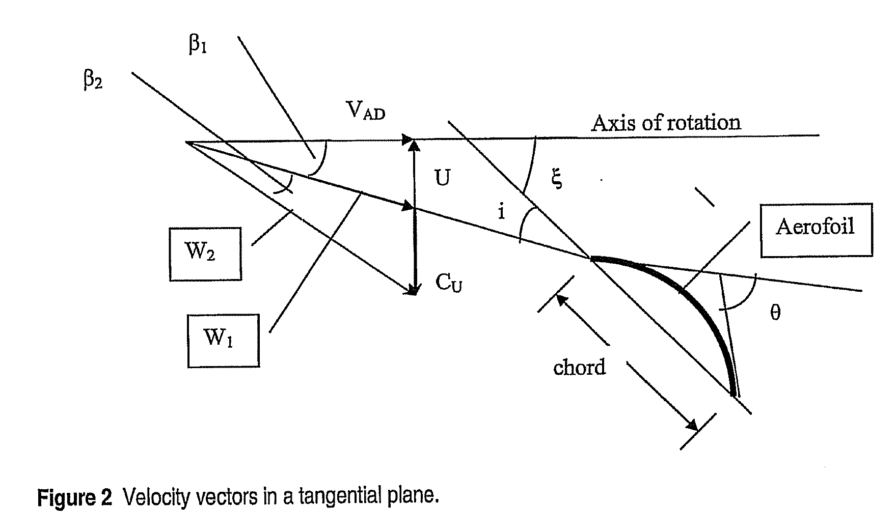
[0047]An advantage of using simple cambered plate aerofoils is that they are cheap to produce, thereby enabling the manufacture of an inexpensive turbine of simple and robust construction. Advantageously, the camber angle θ of the aerofoil varies from 10-15 degrees at the tip of the blades to 25-30 degrees at the hub.
[0052]Preferably the method includes the further step of selecting an alternative value for at least one of the design parameters and repeating steps (b) to (f) so as to optimise the blade characteristics to maximise energy extraction from the air flow at the lowest rotational speed of the rotor.
[0054]Once again, this method preferably includes the further step of selecting an alternative value for at least one of the design parameters and repeating steps (b) to (s) so as to optimise the blade characteristics to maximise energy extraction from the air flow at the lowest rotational speed of the rotor.
[0063]Again, this method preferably includes the further step of selecting an alternative value for at least one of the design parameters and repeating steps (b) to (s) so as to optimise the blade characteristics to maximise energy extraction from the air flow at the lowest rotational speed of the rotor.

Problems solved by technology

Wind turbines developed in recent decades for this purpose, as opposed to being for agricultural purposes, are generally very large, complex and expensive to manufacture.
The Cobden turbine was far less complex and far less expensive to manufacture than a typical high speed power generation turbine, but it was also far less efficient.
However, in high wind speeds, complex speed limiting mechanisms must be employed to prevent the turbine self destructing.
It did not need complex control mechanisms to prevent it over speeding but its performance was limited.
Actuator disk theory yields equation (a) above for turbine maximum power, however, actuator disk theory does not yield the rotor geometry without further design theory.

Method used


Image

  • Wind Turbine
  • Wind Turbine
  • Wind Turbine

Examples


Embodiment Construction

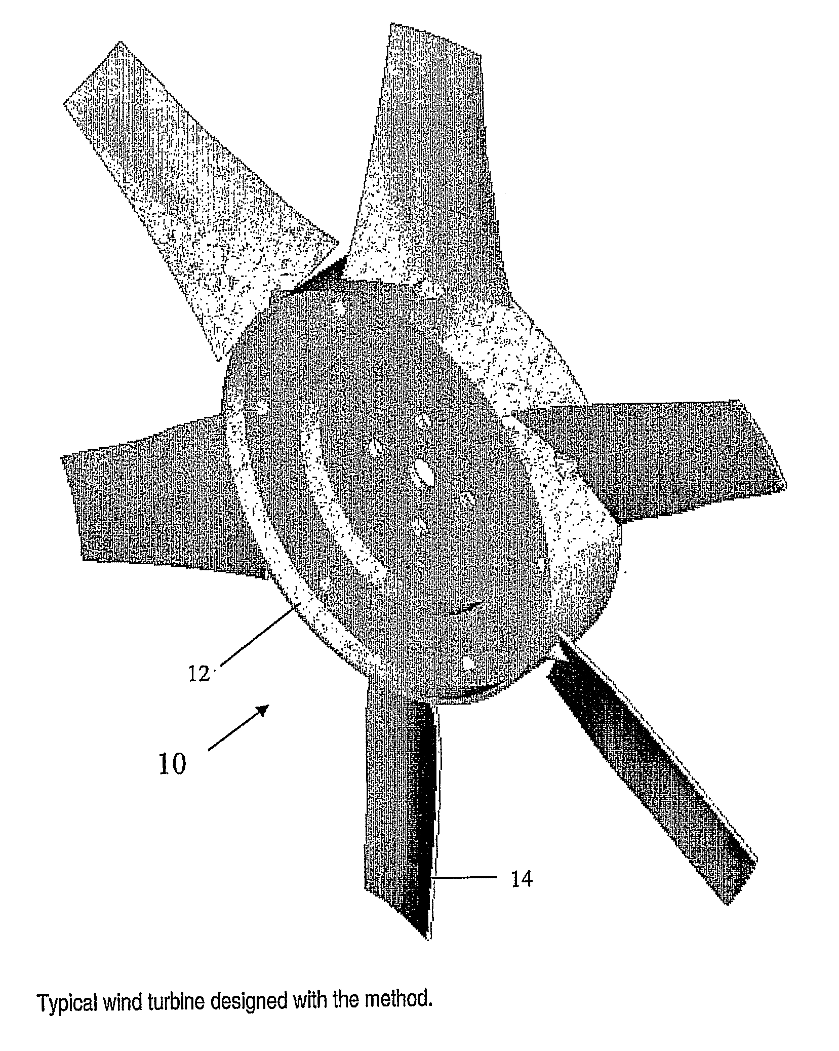
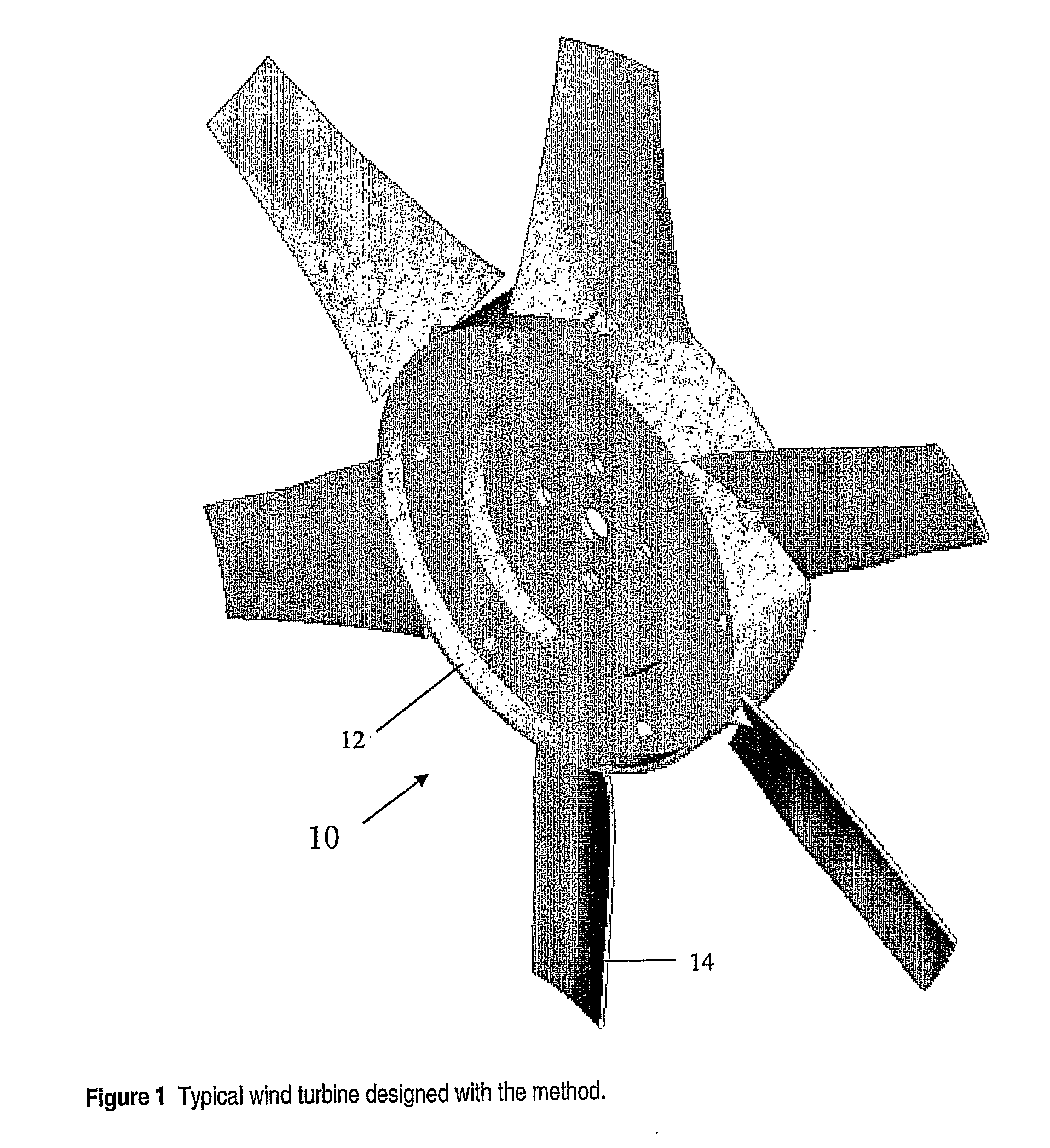
[0074]Referring to the drawings, FIG. 1 shows a rotor10 for a horizontal axis wind turbine which has been designed in accordance with a preferred embodiment of the present invention. The rotor 10 includes a hub 12 and a plurality of blades 14 extending radially from the hub 12. The blades 14 are shaped such that in operation, at any selected radial position along the length of the blades, the ratio of air whirl velocity CU leaving the blades in the direction of blade rotation divided by axial wind speed upstream of the rotor VA is given by:

CUVA=49λ

[0075]wherein λ is the local speed ratio at the selected radial position and is given by

λ=UVA

[0076]wherein U is the circumferential blade speed at the selected radial position.

[0077]The following is a detailed description of a process for defining the shape of the blades to meet this requirement. This preferred form of the process, which is given by way of illustration only, is specifically directed to the design of small, slow speed, effi...


PUM


Abstract

A method of designing a rotor for a horizontal axis wind turbine. The method combines an actuator disk analysis with a cascade fan design method to define the blade characteristics, including the shape and size of the blades, such that the maximum amount of energy is extracted from the air at the lowest rotational speed. A method of manufacturing a wind turbine and a turbine designed in accordance with the method are also disclosed.

Description

FIELD OF THE INVENTION[0001]The present invention relates generally to wind turbines. In particular, the invention concerns small, low speed, horizontal axis wind turbines.BACKGROUND OF THE INVENTION[0002]With concerns about global warming growing, there has been increasing interest in the generation of electricity by harnessing the power of the wind. Wind turbines developed in recent decades for this purpose, as opposed to being for agricultural purposes, are generally very large, complex and expensive to manufacture. Modern horizontal axis wind turbines of the “high-speed” type, as used in large scale power generation, typically include two or three propeller-style blades with a diameter of 100 meters or more. The tip speed ratio of such turbines is often in the region of 7.0.[0003]In contrast, small “low-speed” turbines have also been developed and these usually include a larger number of smaller blades. One example of such a turbine was described by Cobden in U.S. Pat. No. 4,415...

Claims


Application Information

Patent Timeline
IPC IPC(8): F03D1/06
CPCF03D1/0608Y02E10/721F05B2240/301F05B2240/30Y02E10/72Y02P70/50
Inventor O'CONNOR, ARTHUR BENJAMINGRAINGER, CLIVE FILLEUL
Owner HUSH WIND ENERGY LTD
Learn More