Deployable segmented tlif device

a segmented tlif and segmented technology, applied in the field of tlif devices deployed, can solve the problems of preventing the disc from performing the functions of the disc, reducing the disc height, and affecting the function of the disc,

Inactive Publication Date: 2008-09-11
ZIMMER SPINE INC
View PDF22 Cites 182 Cited by
  • Summary
  • Abstract
  • Description
  • Claims
  • Application Information

AI Technical Summary

Benefits of technology

[0005]The present invention is premised on the realization that an insert formed from a plurality of generally trapezoidal segments can be inserted between adjacent vertebrae to maintain a desired disc space. More particularly, the present invention utilizes a plurality of interconnected trapezoidal segments, which, upon insertion into a disc space, can be drawn into a generally arcuate shape

Problems solved by technology

The intervertebral disc can be damaged in many ways.
Mechanical damage can be caused by herniation in which a portion of the nucleus projects through an opening or tear in the annulus.
In such situations, there may be a decrease in the internal nucleus volume resulting in a decrease in disc height preventing the disc from performing its designed functions.

Method used


Image

  • Deployable segmented tlif device
  • Deployable segmented tlif device
  • Deployable segmented tlif device

Examples


Embodiment Construction

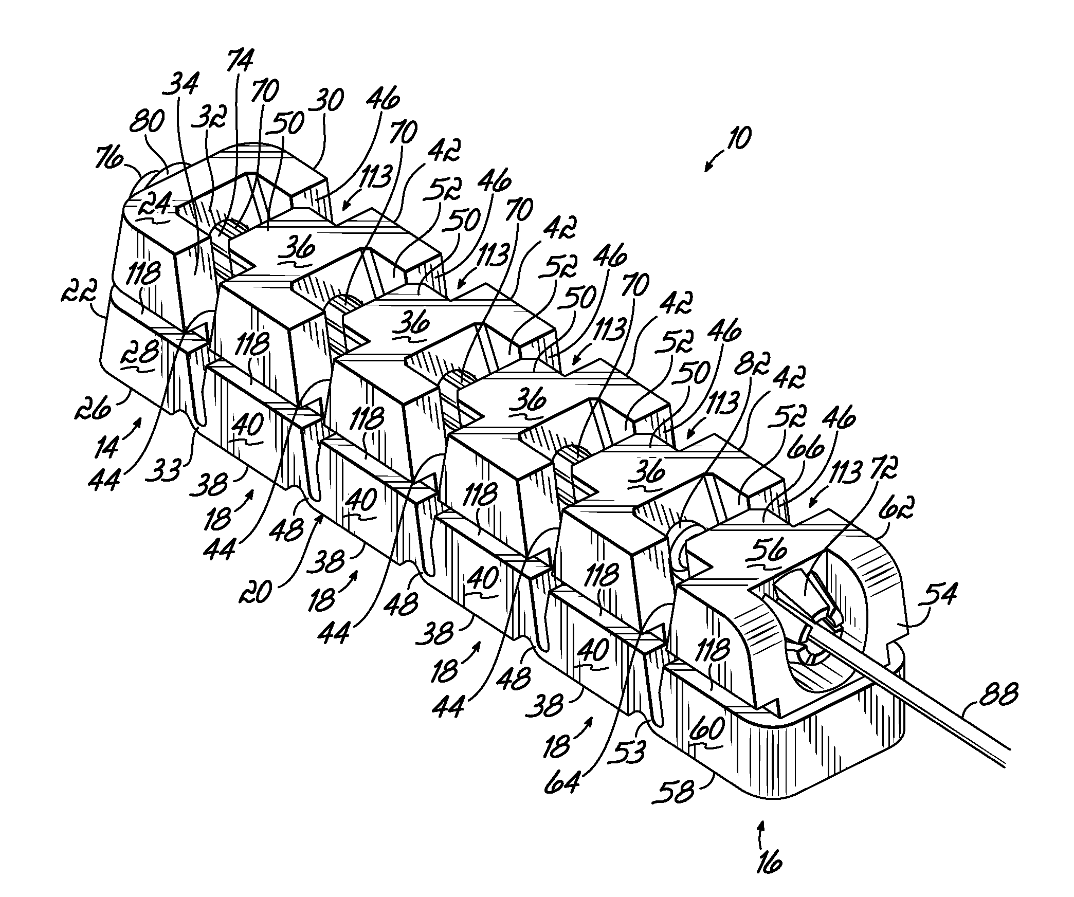
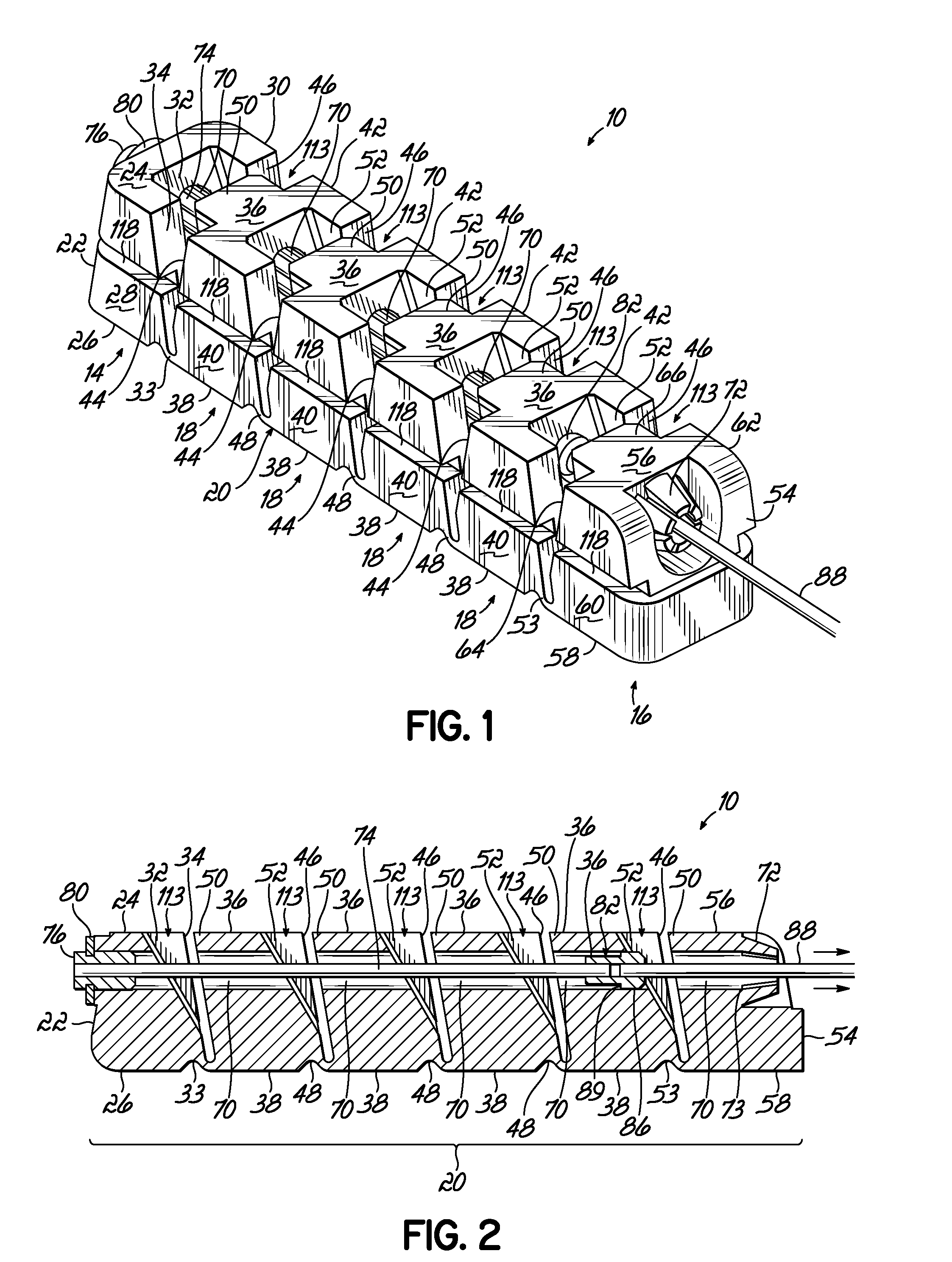
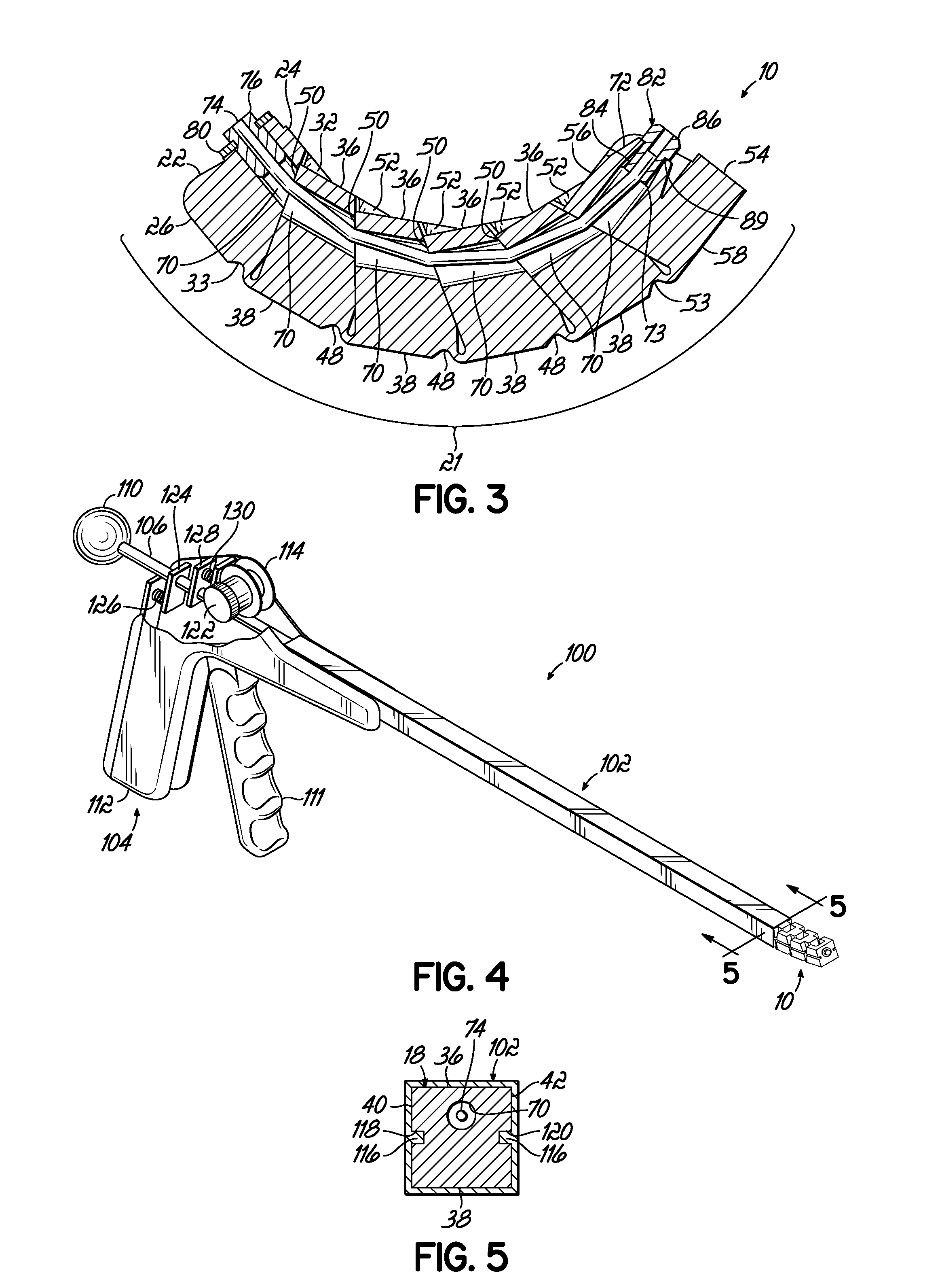
[0016]The present invention is an intervertebral support 10 that is designed to be implanted within the intervertebral space between adjacent vertebrae. The support 10 includes a leading segment 14, a terminal segment 16 and a plurality of intermediate segments 18. In one embodiment, four intermediate segments are included. In other embodiments, more or less intermediate segments can be utilized depending on factors such as patient anatomy or implant positioning. The segments 14, 16 and 18 are connected together by a continuous connective portion 20 along the base of the segments 14, 16 and 18 that following implantation forms an anterior wall 21 of the implant (FIG. 7).

[0017]The leading segment 14 includes a rounded leading end 22, radially inner side 24, radially outer side 26, and mirror image top 28 and bottom 30 sides. The leading segment 14 can optionally be configured to have a tapered or wedge shaped leading end 22 to facilitate implantation. The terms “radially inward”, “ra...


PUM


Abstract

A segmented intervertebral body fusion support includes a plurality of segments, the segments including an initial segment, a final segment and at least one intermediate segment. The intermediate segment has a generally trapezoidal configuration and the initial and final segments include tapered side walls providing triangular gaps between adjacent segments. A draw wire is fixed to the first segment and passes through the remaining segments. By pulling the draw wire relative to the segments, the segments are drawn together in a generally arcuate configuration. The draw wire includes an enlargement that passes through the final segment and engages a plurality of fingers on the final segment, which prevents the draw wire from retracting, maintaining the arcuate configuration. The segmented device can be inserted through a laparoscopic device into the intervertebral space and can be subsequently drawn into the arcuate configuration to establish the desired intervertebral spacing.

Description

BACKGROUND OF THE INVENTION[0001]Intervertebral discs serve several functions. A primary function of the intervertebral disc is to facilitate mobility of the spine. In addition, the disc provides load bearing, load transferring, and shock absorption between vertebral discs. The disc itself is formed of two major components, a gelatinous nucleus pulposus which is surrounded by an annulus fibrosis.[0002]The intervertebral disc can be damaged in many ways. Mechanical damage can be caused by herniation in which a portion of the nucleus projects through an opening or tear in the annulus. Progressive degeneration can be caused by either genetic or biochemical problems. In such situations, there may be a decrease in the internal nucleus volume resulting in a decrease in disc height preventing the disc from performing its designed functions.[0003]One way to relieve the symptoms of a ruptured or deteriorated disc is by surgical removal of a portion or all of the intervertebral disc. Removal ...

Claims


Application Information

Patent Timeline
IPC IPC(8): A61F2/44
CPCA61F2/4455A61F2250/0071A61F2002/30112A61F2002/30153A61F2002/30266A61F2002/30462A61F2002/30471A61F2002/305A61F2002/30561A61F2002/4415A61F2220/0025A61F2220/0075A61F2220/0091A61F2230/0004A61F2230/0019A61F2230/0082A61F2/4611
Inventor VIKER, THOMAS O.
Owner ZIMMER SPINE INC
Why Eureka
Try Eureka