
Spinal interbody spacer device

a technology of interbody spacer and interbody, which is applied in the field of medical devices, can solve the problems of degeneration of one or more discs, limited ability of existing spacers to extract and reposition interbody spacer devices, and limitations of current devices, systems, and surgical procedures

Active Publication Date: 2008-09-11
THE CENT FOR ORTHOPEDIC RES & EDUCATION
View PDF22 Cites 47 Cited by
  • Summary
  • Abstract
  • Description
  • Claims
  • Application Information

AI Technical Summary

Benefits of technology

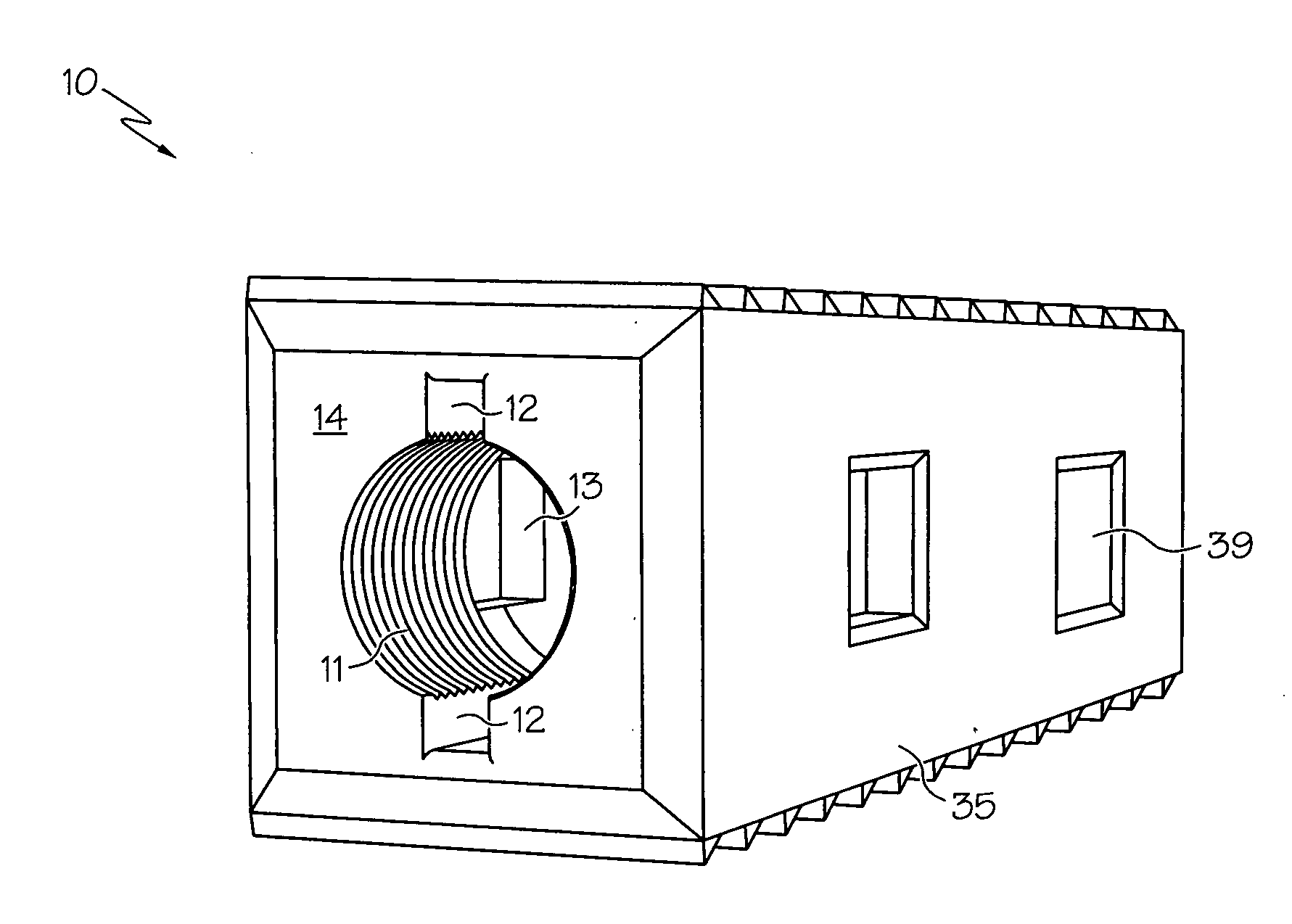
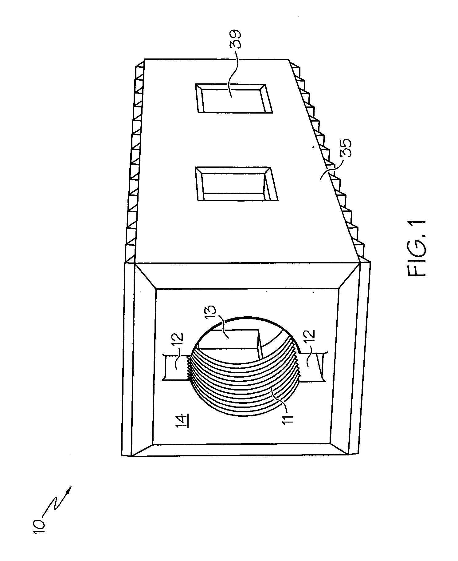
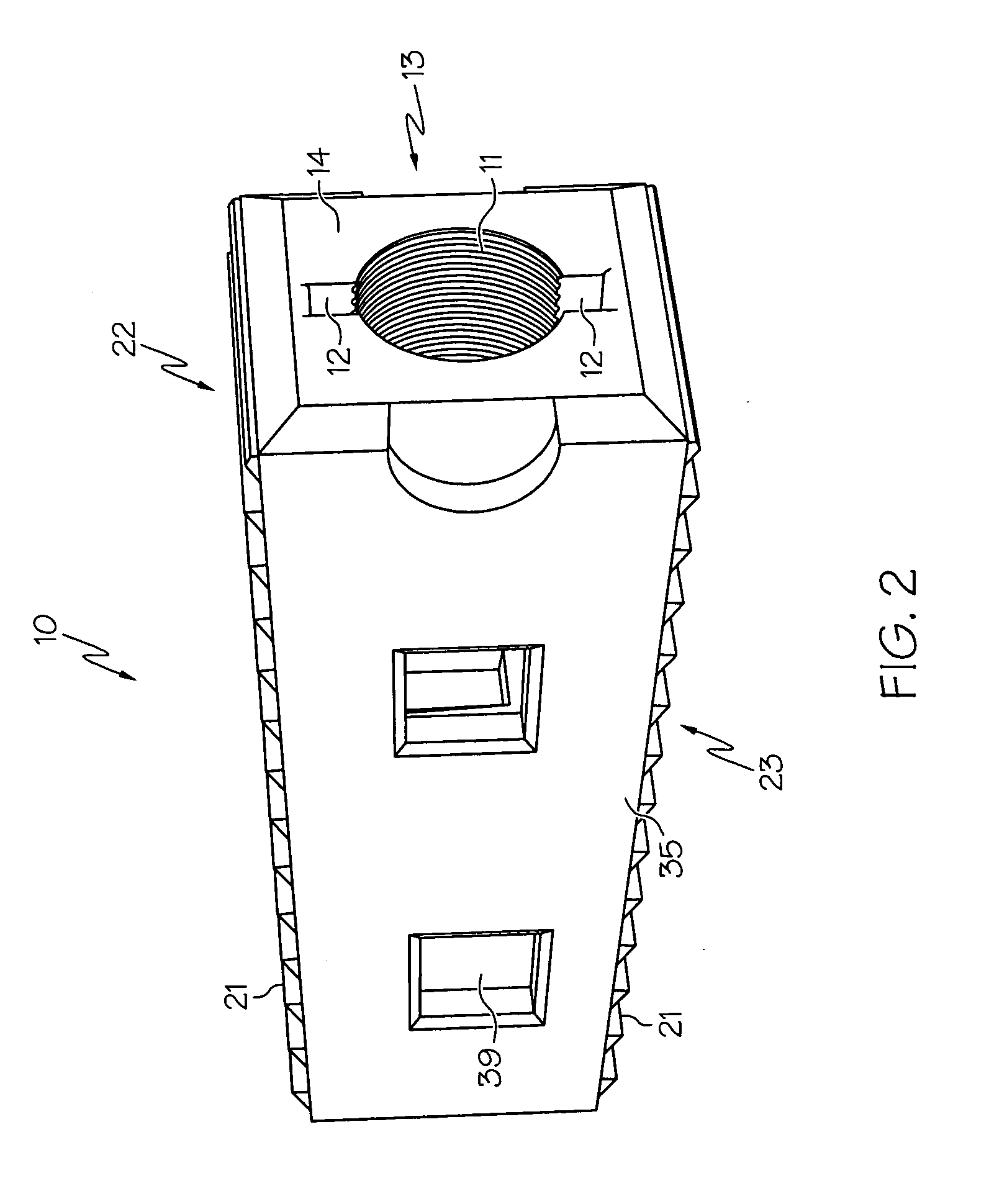
[0010]In a further embodiment, still by way of example only, there is provided a method for manipulating a spinal interbody spacer for use in spinal surgery on a patient, in which the method includes the steps of: attaching a positioning tool to a spacer by screwing a threaded end of the positioning tool to threaded receiving aperture of the spacer; manipulating the positioning tool so as to locate the spacer in a desired location; and removing the positioning tool by unscrewing it from the threaded portion of the spacer. The method may further include the step of receiving positioning information from the spacer through radio opaque markets located in the spacer. Additionally the method may include the step of attaching a positioning tool and contacting a contact face positioned on the positioning tool with a reciprocal face positioned on the spacer so as to transfer force from the positioning tool to the spacer. Additionally, the method allows the step of securing the spacer to the surgical patient. Finally, the method may be used with further steps such as: sliding the tip of an extraction tool through an aperture in the spacer; rotating the tip of the extraction tool until tabs located on the extraction tool contact blocks positioned on the spacer; and pulling on the extraction tool so as to exert a force on the spacer.

Problems solved by technology

When a spinal disc has suffered disease or trauma, degeneration of one or more discs may result.
However, the existing spacers suffer from a limited ability to extract and reposition the interbody spacer device.
This limitation is experienced in current devices, systems, and surgical procedures.
This limitation introduces additional potential risks to the patient.
With current systems and procedures, the need to remove or reposition an interbody spacer can present a significant risk to the patient's spinal cord, nerve roots, and dural sack.
Similarly, a surgeon may settle for an imperfect placement due to the risk associated with introducing tools to reposition the device and a lack of options for repositioning.
This may be due to incorrect initial positioning by the surgeon, infection shortly after surgery, or failure of a vertebral body.
These issues usually become apparent within several weeks after initial surgery.

Method used


Image

  • Spinal interbody spacer device
  • Spinal interbody spacer device
  • Spinal interbody spacer device

Examples


Embodiment Construction

[0027]The following detailed description of the invention is merely exemplary in nature and is not intended to limit the invention or the application and uses of the invention. Furthermore, there is no intention to be bound by any theory presented in the preceding background of the invention or the following detailed description of the invention. Reference will now be made in detail to exemplary embodiments of the invention, examples of which are illustrated in the accompanying drawings. Wherever possible, the same reference numbers will be used throughout the drawings to refer to the same or like parts.

[0028]There is now described a set of elements which may be used in combination as an assembly or individually as an instrument set or a medical or surgical kit. Furthermore a method will be described for advantageously using the elements of the kit so as to overcome limitations previously described in the prior art for spinal spacers and implants.

[0029]Referring now to FIG. 1, the f...


PUM


Abstract

There is described an instrument set for use in spinal surgery that includes as elements a spinal body spacer, a placement tool, and an extraction tool. The spacer may be constructed with a body having a first wall and a second wall connected by a top face, a bottom face, and a lateral support. Further, the spinal body spacer has a threaded opening and keyways connected to the threaded opening positioned in a face. The spinal body spacer may also include a superior surface and an inferior surface with a plurality of antimigration furrows positioned on each of the superior surface and the inferior surface. The spacer may have an outer face positioned around the opening and the placement tool may also have a contact face such that the contact face comes into contact with the outer face when the placement tool is fully connected with the spacer. The placement tool has a threaded tip for connecting with the threaded opening of the spacer. The extraction tool has a tip configured to pass through the opening of the spacer, and the tool has tabs positioned on the tip such that the tabs pass through the keyways of the spacer. The extraction tool is configured such that it passes through the aperture, rotates, and then can be used to exert a pulling force on the spacer. The tip of the extraction tool may be a substantially blunt tip, a substantially pointed tip, or even a tip with a hollow area. The spacer may have at least one block disposed on an interior surface such that the block contacts the tabs of the extraction tool thereby restricting rotation of the extraction tool relative to the spacer. The spacer may have a backing plate, and the backing plate may itself include projections disposed in the matrix of the spacer.

Description

CROSS REFERENCE TO RELATED APPLICATIONS[0001]This application claims priority from the provisional patent application Ser. No. 60 / 904,691 filed Mar. 1, 2007 in the name of A. Joshua Appel and Marc C. Jacofsky entitled “Spinal Body Interfacer Device” incorporated herein by reference.FIELD OF THE INVENTION[0002]The present invention relates to medical devices. More particularly, the invention relates to interbody spacer devices and methods for their placement and extraction in spinal surgeries and therapies.BACKGROUND OF THE INVENTION[0003]Interbody spacers are used as aids in various spinal surgeries. When a spinal disc has suffered disease or trauma, degeneration of one or more discs may result. Depending on the medical indications of the damaged spine, a surgical treatment may be called for. For example, spinal surgeries may call for the full or partial removal of a spinal disc. In other procedures, an implant or support may be used to stabilize elements of the spine in order to as...

Claims


Application Information

Patent Timeline
Patent Type & Authority Applications(United States)
IPC IPC(8): A61F2/44A61B17/58
CPCA61B17/92A61F2/447A61F2/4611A61F2002/2835A61F2002/4629A61F2002/3082A61F2002/4475A61F2002/4619A61F2002/4627A61F2002/30594A61F2002/30593
Inventor JACOFSKY, MARC C.APPEL, A. JOSHUA
Owner THE CENT FOR ORTHOPEDIC RES & EDUCATION
Learn More