System and method for infrastructure reporting

a technology of infrastructure reporting and system and method, applied in the field of infrastructure reporting, can solve the problems of inconvenient and often non-productive, difficult or impossible to generate information, and inability to achieve sophisticated equipment,

Inactive Publication Date: 2008-09-11
OPTIMAL INNOVATIONS INC
View PDF13 Cites 98 Cited by
  • Summary
  • Abstract
  • Description
  • Claims
  • Application Information

AI Technical Summary

Benefits of technology

[0007]A plurality of devices are interconnected via a utility and distributed throughout a premises with each device operable for being temporarily configured to provide a service as well as information desired by a user. In one embodiment, the service is selected from the utility list of: light switch, power outlet, thermostat while the information is selected from the list of: environmental condition, power consumption, power grid conditions, security condition, telephony, building automation conditions, Internet access, announcements, an

Problems solved by technology

If a home owner or infrastructure dweller were to try at any point in time to monitor the power usage, or any other operating parameter (such as the average temperature, the power usage, the occupancy pattern, the light levels, the highest or lowest temperature a room, or the refrigerator, achieved during the preceding 12 hours) that information would be difficult or impossible, to generate without

Method used


Image

  • System and method for infrastructure reporting
  • System and method for infrastructure reporting
  • System and method for infrastructure reporting

Examples


Embodiment Construction

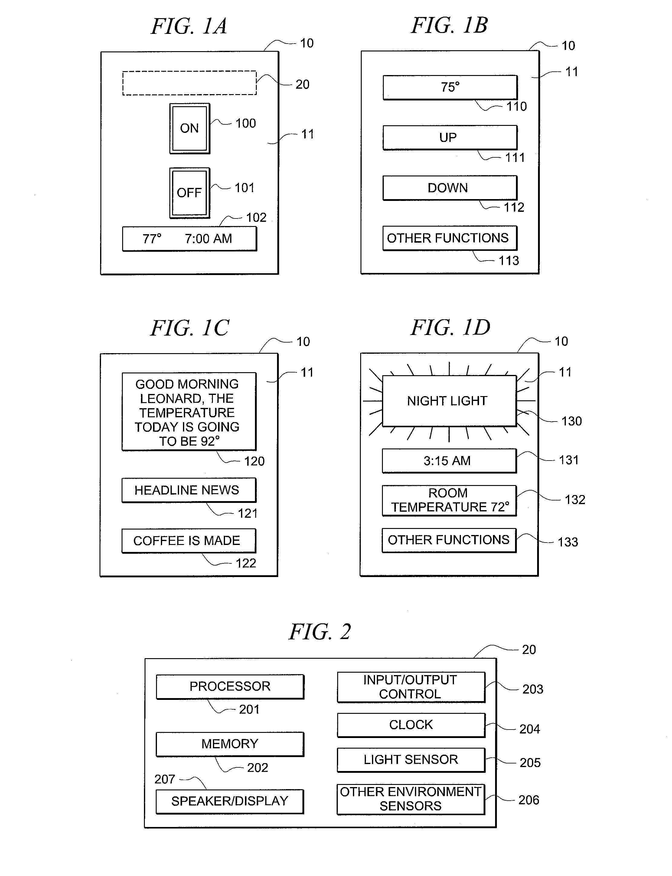
[0013]FIGS. 1A through 1D illustrate embodiments of a device in accordance with the inventive concepts hereof.

[0014]FIG. 1A illustrates device 10 wherein screen 11 is configured as a conventional light power switch having on button 100 and off button 101. A user then can, by touching on button 100 turn a light, or other electrical device, on. Likewise, touching off button 101 will turn the electrical device off. If desired, screen 11 can also be configured with temperature and time display 102. As will be discussed hereinafter, device 10 is controlled by a controller, such as controller 20, which can be internal to device 10 or external thereto, or a combination of each.

[0015]Screen 11 can be a touch sensitive screen designed in the well-known manner such that different keys' functions can be displayed from time to time in anticipation of a user's needs at that time. For example, during the day, as determined either from clock 204 (FIG. 2) or from other environmental sensors 206 (su...


PUM


Abstract

A plurality of devices are interconnected via a utility and distributed throughout a premises with each device operable for being temporarily configured to provide a service as well as information desired by a user. In one embodiment, the service is selected from the list of: light switch, power outlet, thermostat and the information is selected from the list of: environmental condition, power consumption, power grid conditions, Internet access, announcements. If desired, one or more devices can be configured from time to time in anticipation of the user's needs at that time.

Description

CROSS-REFERENCE TO RELATED APPLICATIONS[0001]The present application is related to concurrently filed, co-pending, and commonly-assigned; U.S. patent application Ser. No. ______, Attorney Docket No. 66816 / P012US / 10609934, entitled “SYSTEMS AND METHODS FOR LINKING UTILITY CONTROL DEVICES”; U.S. patent application Ser. No. ______, Attorney Docket No. 66816-P014US-10614006, entitled “LIGHT SWITCH USED AS A COMMUNICATION DEVICE”; U.S. patent application Ser. No. ______, Attorney Docket No. 66816-P015US-10614005, entitled “SYSTEM AND METHOD FOR PREMISES MONITORING USING WEIGHT DETECTION”; U.S. patent application Ser. No. ______, Attorney Docket No. 66816-P016US-10614296, entitled “ANTICIPATORY UTILITY CONTROL DEVICE”; U.S. patent application Ser. No. ______, Attorney Docket No. 66816-P017US-10614295, entitled “PLUG AND PLAY MODULAR POWER CONTROL MODULES”; and U.S. patent application Ser. No. ______, Attorney Docket No. 66816-P018US-10701603, entitled “SYSTEM AND METHOD FOR SUBSTITUTING D...

Claims


Application Information

Patent Timeline
IPC IPC(8): G06F17/00G06F3/048
CPCG05B19/042G05B2219/23377G05B2219/25092G05B2219/2642Y04S20/228H04L2012/285Y02B70/3241Y02B70/325Y04S20/227H04L12/2829G05B15/02H04M11/00Y02B70/30Y04S20/20
Inventor SCHOETTLE, ROLAND
Owner OPTIMAL INNOVATIONS INC
Why Eureka
Try Eureka