
Bath and shower assist means

a technology for showers and showers, applied in the field of bath and shower assist means, can solve the problems of affecting many households, physical normal and able-bodied are also vulnerable, and the use of grab bars, and achieve the effect of providing lateral stability to the grab bars and easy installation, removal or transfer

Inactive Publication Date: 2008-09-18
GRANT WILLIE T
View PDF3 Cites 25 Cited by
  • Summary
  • Abstract
  • Description
  • Claims
  • Application Information

AI Technical Summary

Benefits of technology

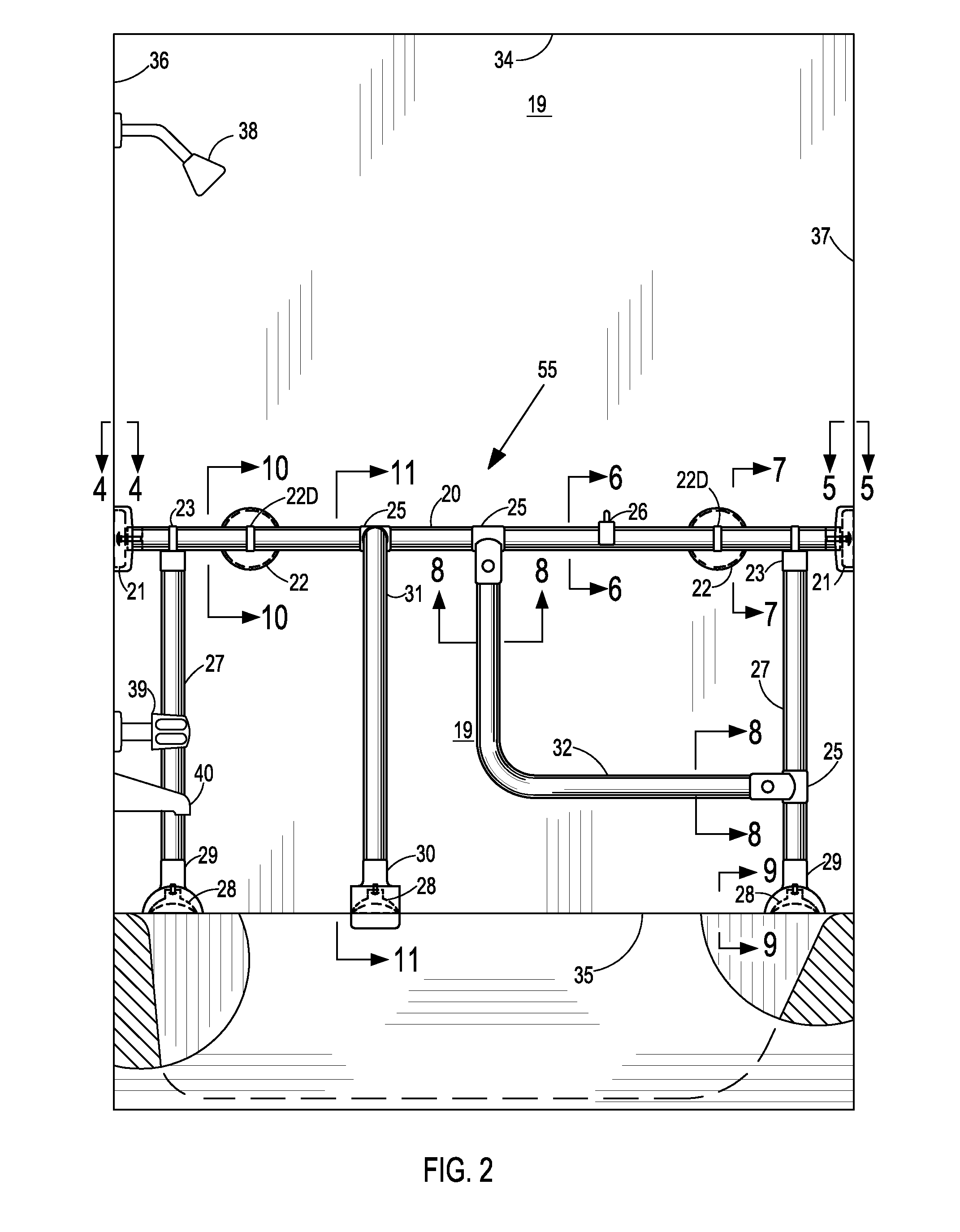
[0005]The present invention overcomes these shortcomings and other limitations by providing assist means that do not require mechanical fasteners for installation in shower and tub / shower facilities. Therefore, the assist means are easily installed, removed or transferred from one location to another without involving mechanical fasteners in the process. The grip means part of the invention is a horizontal, rotatable grip bar extending from a first wall of a shower or tub / shower enclosure to a second wall that is opposite and generally parallel to the first wall. The grip bar parallels a third wall of the enclosure. Compressible means having significant gripping power attaches to each end of the horizontal bar and engages the first and second walls when the horizontal grip bar is rotated about its longitudinal axis. This causes the compressible means to experience a compressive axial force substantially clamping the bar between the walls engaging the compressible means. Suction means such as suction cups or vacuum cups attached to brackets encircling the grip bar are mounted perpendicular to the bar and the parallel wall. The suction cups develop tensile forces that secure the grip bar to the wall, thereby providing lateral stability to the bar when the user showers in either a shower enclosure or in a tub / shower facility.
[0006]Where the user has tub / shower accommodations but predominately bathes, the present invention includes vertical supports attached to the horizontal grip bar. The vertical supports strengthen the grip bar permitting the user to pull up from a sitting to a standing position using a lift bar attached to the grip bar and a vertical support. The vertical supports also transform the grip bar into a means capable of withstanding the safety loading prescribed by state codes for ADA compliance. Further, to aid in entering and exiting a bathtub, an entry bar attaches to the horizontal grip bar spanning across the tub and descending vertically to engage the opposite rim of the bathtub by means of a bracket.
[0007]For the user having a free-standing bathtub in an area without adjacent walls; the vertical supports extend from the rim of the bathtub to the ceiling terminating with compressible means. The horizontal grip bar connects to the vertical supports. The user also has the entry bar and the lift bar available as previously described. Thus the present invention provides users of shower and bath facilities secure means of support and assistance on entering and exiting each facility.
[0008]One of the principal objectives of the present invention is to provide assist means that can be easily assembled, installed, and removed without the use of mechanical fasteners.
[0010]Another objective is to provide assist means that can be easily adjusted vertically within the enclosure.
[0011]Another objective is to provide grip means with calibrated means making the installation of the grip means independent of the varying strength of the installers.

Problems solved by technology

It is well recognized by those who are safety conscious that falls in the home, particularly in the bathroom, are a serious problem that impacts many households.
Especially are the elderly and physically disadvantaged susceptible; although the physically normal and able-bodied are also vulnerable.
Although portable grab bars are available, they are really assist bars only for they cannot meet the prescribed minimum safety loadings of state codes.
There are also circumstances that may require the use of a grab bar for a limited period of time.
The process accompanying this decision can result in a noticeable expense for the limited time the fixed bar was in service.

Method used


Image

  • Bath and shower assist means
  • Bath and shower assist means
  • Bath and shower assist means

Examples


Embodiment Construction

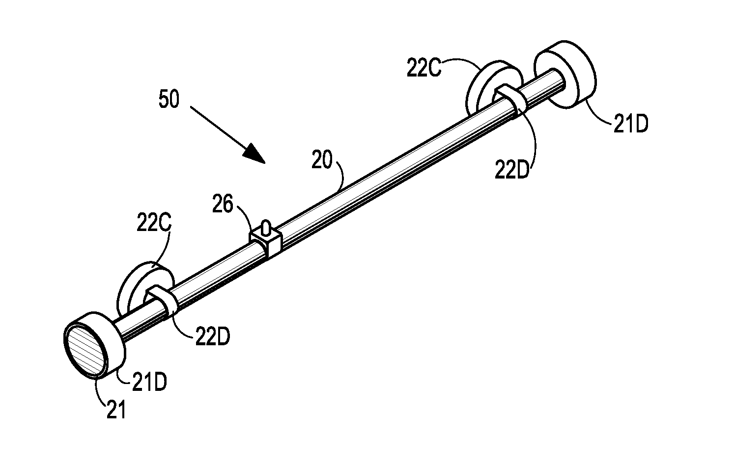
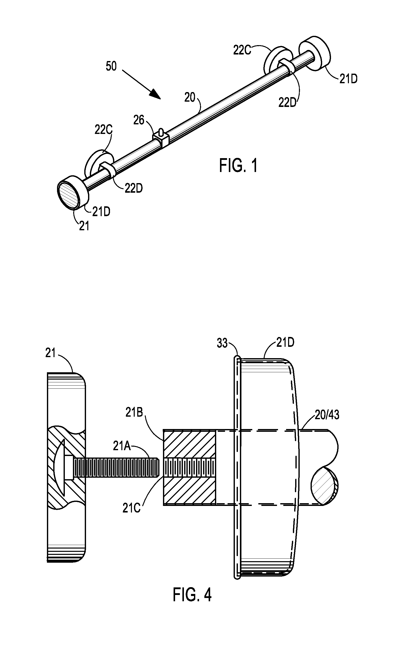
[0027]Referring to the views specifically, FIG. 1 shows grip means 50 constructed according to the present invention for installation in a shower enclosure and tub / shower enclosure having walls defined by numbers 19, 36, and 37 and ceiling 34 of FIG. 2. Included also in FIG. 2 is bathtub 35, with shower head 38, faucet 39, and spout 40. The grip means comprises grip bar 20 rotatively connecting to compressible means 21 shown in FIG. 2 and, more distinctly, in FIGS. 4 and 5. As shown in FIG. 4, grip bar 20 seats insert 21B; said insert having internal threads 21C to engage external threads of stud 21A; said stud being fixedly embedded in compressible means 21. Said compressible means comprises suction cups, disks, covered with or constructed of compressible material, or like means; each capable of expelling air trapped between face of said compressible means and a parallel surface and forcefully gripping said surface under the influence of an externally applied compressive force. FIG...


PUM


Abstract

Assist means to aid users of bath and shower facilities; said means having installation independent of the typical screw type wall fasteners. Assist means comprising a horizontal grip bar having longitudinal, lateral, and vertical restraints. The longitudinal restraints consist of compressible means rotatively attaching to each extremity of the grip bar. Said lateral restraints comprise tensile means, suction cups, or like means, securing the grip bar to an enclosure wall parallel to the bar. During installation the grip bar is rotated about its longitudinal axis, causing the compressible means at each extremity to forcefully engage an enclosure wall. The vertical restraints connect to the grip bar and to lower compressible means that secure said restraints to the rim of a bathtub. A tub entry-exit bar and lift bar attaching to said grip bar provide safe assistance for the user.

Description

BACKGROUND OF THE INVENTION[0001]It is well recognized by those who are safety conscious that falls in the home, particularly in the bathroom, are a serious problem that impacts many households. Especially are the elderly and physically disadvantaged susceptible; although the physically normal and able-bodied are also vulnerable. The American Disability Act (ADA) mandates the installation and use of grab bars in facilities that serve the physically disadvantaged. However, grab bars are also readily available to the general public for installation in private residences as an assist and fall preventive measure when bathing or showering[0002]As practical as it is to install fixed grab bars as a deterrent to falls in bathtubs and showers, testing by an independent agency has shown that their effectiveness can be greatly reduced if improperly connected to supporting walls. In a New York State laboratory test performed by the Eastern Paralyzed Veterans Association (EPVA) in April 2002, on...

Claims


Application Information

Patent Timeline
IPC IPC(8): A47K3/024
CPCA47K3/003
Inventor GRANT, WILLIE T.
Owner GRANT WILLIE T
Learn More