Vehicle front structure

a front structure and vehicle technology, applied in the direction of roofs, vehicle arrangements, transportation and packaging, etc., can solve the problem that the dispersion of impact load may not be properly conducted against a larger crash impa

Inactive Publication Date: 2008-09-18
MAZDA MOTOR CORP
View PDF4 Cites 29 Cited by
  • Summary
  • Abstract
  • Description
  • Claims
  • Application Information

AI Technical Summary

Benefits of technology

[0006]The present invention has been devised in view of the above-described concern, and an object of the present invention is to provide a vehicle front structure with a pair of front side frames provided at both sides of a vehicle body so as to extend in a vehicle longitudinal direction that can disperse the impact load properly even when a considerably large fontal-crash impact load acts.

Problems solved by technology

Accordingly, there is a concern that the proper dispersion of the impact load may not be properly conducted against a larger crash impact.

Method used


Image

  • Vehicle front structure
  • Vehicle front structure
  • Vehicle front structure

Examples


Embodiment Construction

[0029]Hereinafter, a preferred embodiment of the present invention will be described referring to the accompanying drawings.

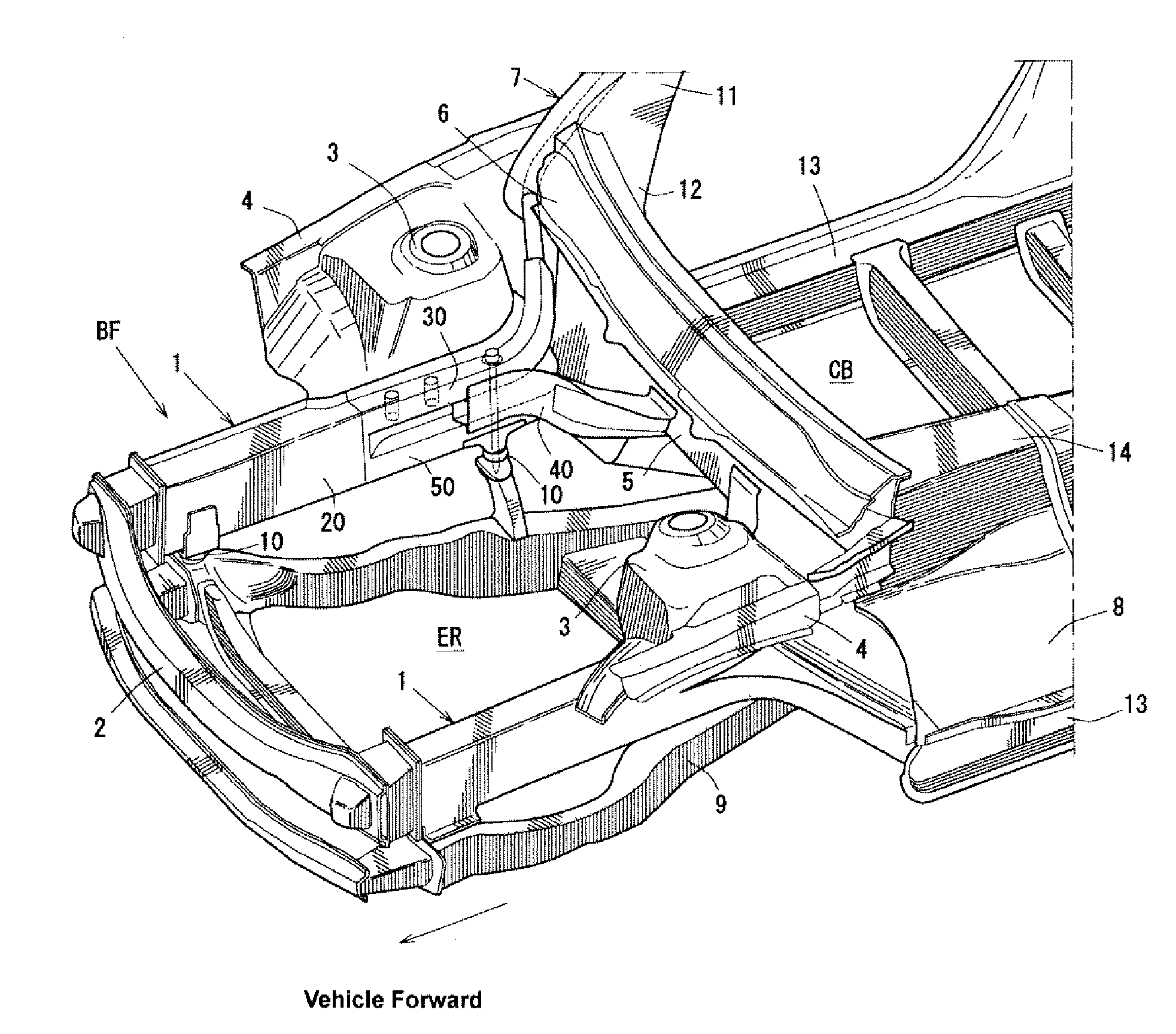
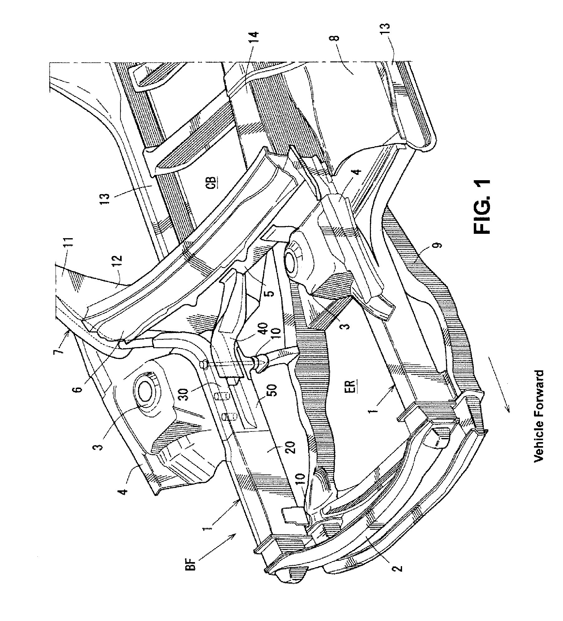
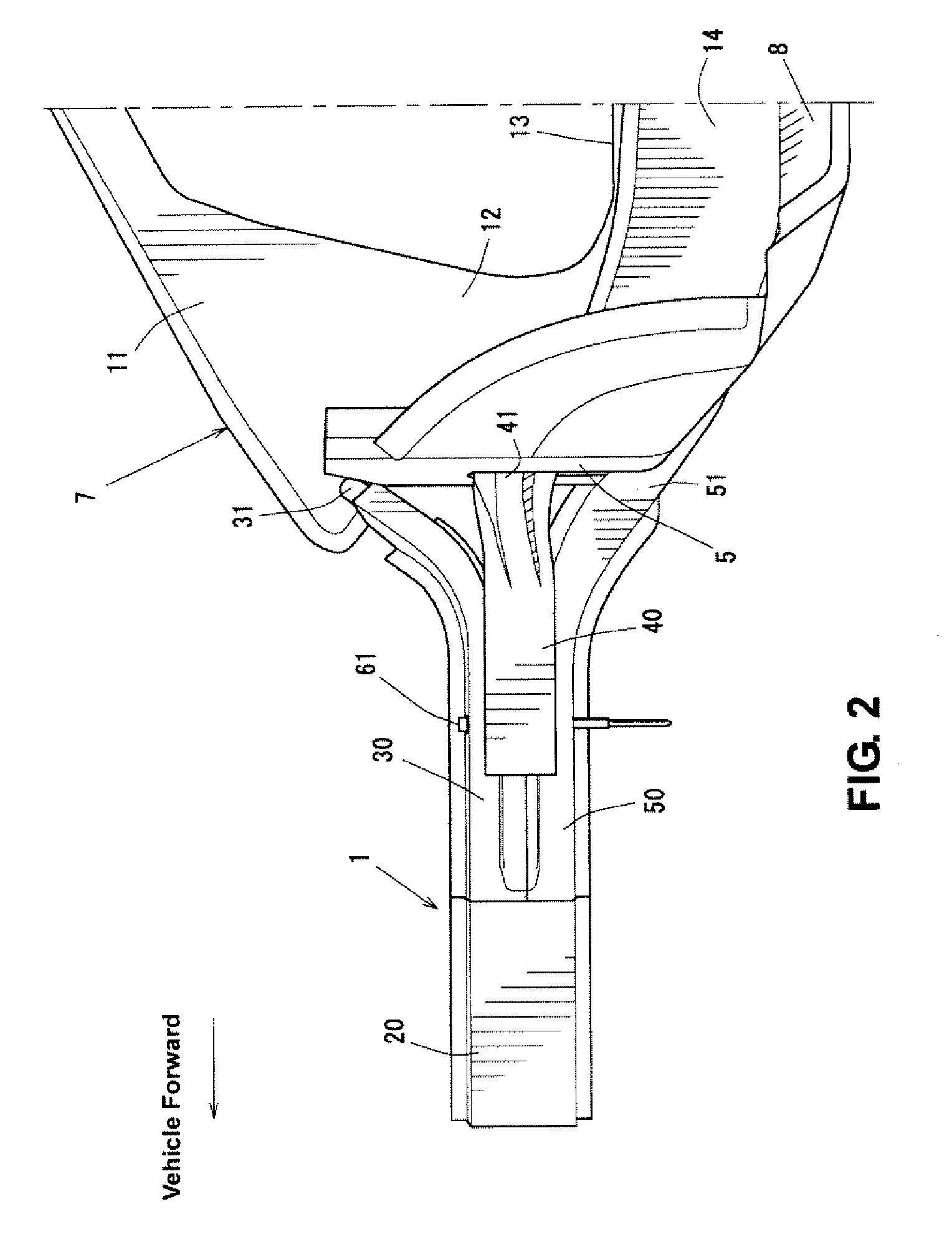
[0030]First, a whole part of a vehicle front structure according to the present embodiment will be described referring to FIGS. 1 through 6. FIG. 1 is a perspective view of a vehicle front structure according to the present embodiment. FIG. 2 is a side view of part of the structure including a right front side frame, when viewed from a vehicle inside. FIG. 3 is a side view of part of the structure including the right front side frame, when viewed from a vehicle outside. FIG. 4 is an elevation view of part of the structure including the right front side frame. FIG. 5 is a plan view of part of the structure including the right front side frame. FIG. 6 is a bottom view of part of the structure including the right front side frame. Herein, FIG. 3 shows a state where an outer panel is removed from a body side panel.

[0031]A vehicle front structure BF, as shown in FIG...


PUM


Abstract

A middle branch frame portion is configured such that a front end portion is connected to a front side frame via s suspension-frame attaching bolt to fasten a suspension frame, a middle portion extends to a tunnel portion that is provided at the center portion in the vehicle width direction so as to project upward, and a rear portion is provided below (vehicle outside) an upper corner portion of the tunnel portion so as to extend along the upper corner portion. Accordingly, there can be provided a vehicle front structure with a pair of front side frames provided at both sides of a vehicle body so as to extend in a vehicle longitudinal direction that can disperse the load properly even when a larger fontal-crash impact load acts.

Description

BACKGROUND OF THE INVENTION[0001]The present invention relates to a vehicle front structure with a pair of front side frames.[0002]Conventionally, a vehicle front structure of an automotive vehicle is known, in which a pair of front side frames is provided at both sides of a vehicle body so as to extend in a vehicle longitudinal direction and a vehicle-frontal-crash impact load acting on the front side frames is transmitted to a rear-located member (such as a roof panel) properly.[0003]Japanese Patent Laid-Open Publication No. 2003-182633 and U.S. Pat. No. 7,147,275, for example, have proposed a vehicle structure, in which a middle portion of the front side frame and a front pillar or the like are interconnected by a connection frame that extends substantially vertically and the vehicle-frontal-crash impact acting on the front side frame is dispersed and transmitted to the front pillar or the like via the connection frame.[0004]Herein, it may be preferable that the impact load actin...

Claims


Application Information

Patent Timeline
Patent Type & Authority Applications(United States)
IPC IPC(8): B62D25/08
CPCB62D25/082B62D21/152B62D25/2018
Inventor MIKI, KENJIRO
Owner MAZDA MOTOR CORP
Why Eureka
Try Eureka