Wideband multi-function phased array antenna aperture

a phased array, multi-functional technology, applied in the direction of simultaneous aerial operations, antennas, movable bodies, etc., can solve the problems of limiting the flexibility of the derived architecture, complex and costly multi-function arrays, and limited approaches, so as to reduce the number of radiating elements, reduce the required number of beams, and reduce the cost and complexity of multi-function arrays

Active Publication Date: 2017-07-25
THE UNITED STATES OF AMERICA AS REPRESENTED BY THE SECRETARY OF THE NAVY
View PDF6 Cites 4 Cited by
  • Summary
  • Abstract
  • Description
  • Claims
  • Application Information

AI Technical Summary

Benefits of technology

[0025]The invention overcomes prior art limitations, while still using frequency scaled elements, (i.e. the inter-element spacing of the radiating elements in the array are scaled as a function of frequency), to reduce the number of radiating elements, and hence the cost and complexity of the multi-function arrays. The invention also reduces the required number of beams (or links) from any given part of the aperture and minimizes the bandwidth requirement for both the radiating elements and the electronics behind them. A reduction in the number of beams from any part of the aperture will result in the use of realizable chipset beamformers (see, e.g., D-W Kang, K-J, Koh, and G. M. Rebeiz “A Ku-band Two Antenna Four Simultaneous Beams SiGe BiCMOS Phased Array Receiver”, IEEE Transactions on Microwave Theory and Techniques, pp. 771-780, Vol. 58, NO. 4 (April 2010) (“Kang et al.”)) as well as a decrease in the required bandwidth of the array elements.
[0026]The invention provides novel architectures that can consolidate many functions into a single wideband Multi-Function phased array antenna and reduce the total number of elements needed, thereby reducing the size, weight, power, cost and radar cross section when compared to conventional wideband phased array architectures. These novel architectures use frequency scaled elements to reduce the number of radiating elements; many radiating elements in the aperture are scaled as a function of frequency. These architectures also reduce the number of links needed from any part of the aperture and minimize the bandwidth requirement for both the radiating elements and the electronics behind them by properly dispersing the functions over a large aperture, thus further reducing the size, weight, power and cost requirements.

Problems solved by technology

However, the number of radiating elements needed to avoid grating lobes, at the highest frequency of this wideband antenna aperture, becomes prohibitively large resulting in a complex and costly multi-function array.
2”)), but such approaches are limited, e.g. the latter being limited to symmetric and / or square arrays.
In one approach, the operating frequencies are chosen to be a factor of two apart, limiting the flexibility of the derived architectures.
This large number of elements will make this multi-function array very complex and costly.
This extremely large number of components needed to form this multi-beam architecture further illustrates the complexity and high cost of a conventional multi-functional array.
However, the method discussed by Cantrell et al could not be used here because of the constraint that requires equal beamwidth for all frequencies and arrays, which is not the case for the functions considered here.
However, at Ku-band, this inter-element spacing is larger than the maximum allowed of 11.8 mm for grating lobe free operation and hence will result in the formation of grating lobes.
Since the core has the elements with the smallest inter-element spacing, reducing this spacing will result in a significant increase in the number of elements needed to satisfy the directivity requirement.
This will unnecessarily make the system more complex and costly.
One of the difficulties in implementing this architecture is that the radiating elements in the core region need to have a bandwidth of 12.6, which is very difficult to achieve.
Another issue is that the core of this architecture needs to be able to form eight links simultaneously.
At present, there are no simple and cost effective beamforming techniques that are capable of forming eight simultaneous beams with very small element spacing (5.9 mm) needed for this design.
This significantly increases the number of elements needed at these frequencies and hence also increases the number of components needed, increasing the cost and complexity of the arrays.

Method used


Image

  • Wideband multi-function phased array antenna aperture
  • Wideband multi-function phased array antenna aperture
  • Wideband multi-function phased array antenna aperture

Examples


Embodiment Construction

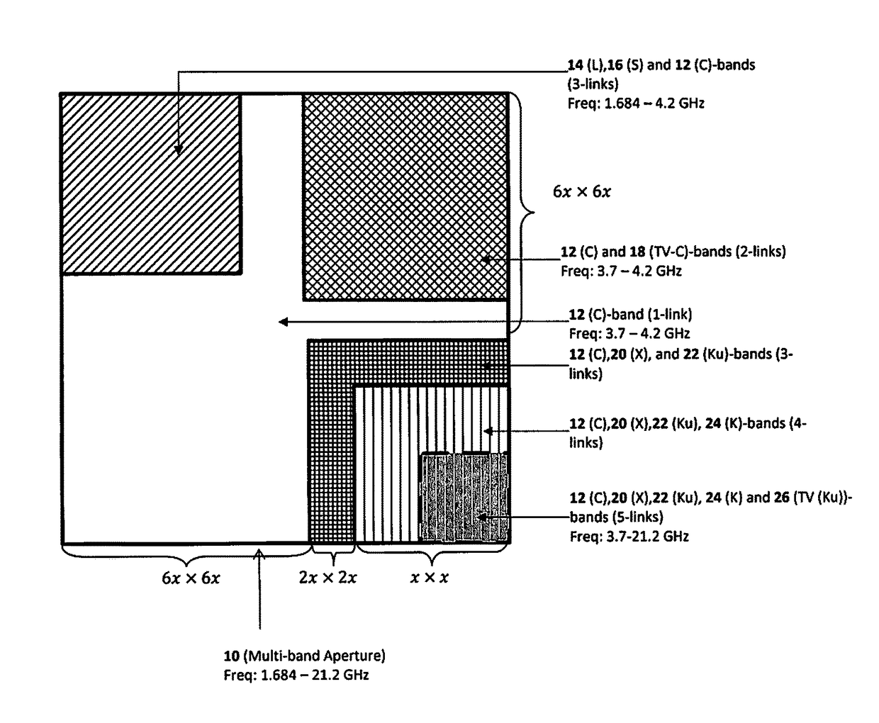
[0038]Definitions: As used herein, C-Band frequencies are a set of radio frequencies ranging from 4 to 8 gigahertz (GHz); K-Band frequencies are a set of radio frequencies ranging from 18 to 27 GHz; Ku-Band frequencies are a set of radio frequencies ranging from 12 to 18 GHz; S-band frequencies are a set of radio frequencies ranging from 2 to 4 GHz; L-band frequencies are a set of radio frequencies ranging from 1 to 2 GHz; X-Band frequencies are a set of radio frequencies ranging from 8.0 to 12.0 GHz; TV(C)-band frequencies are a set of radio frequencies ranging from 4.0 to 4.2 GHz; and TV(Ku)-band frequency is 12.224 GHz.

[0039]Carrier Architectures

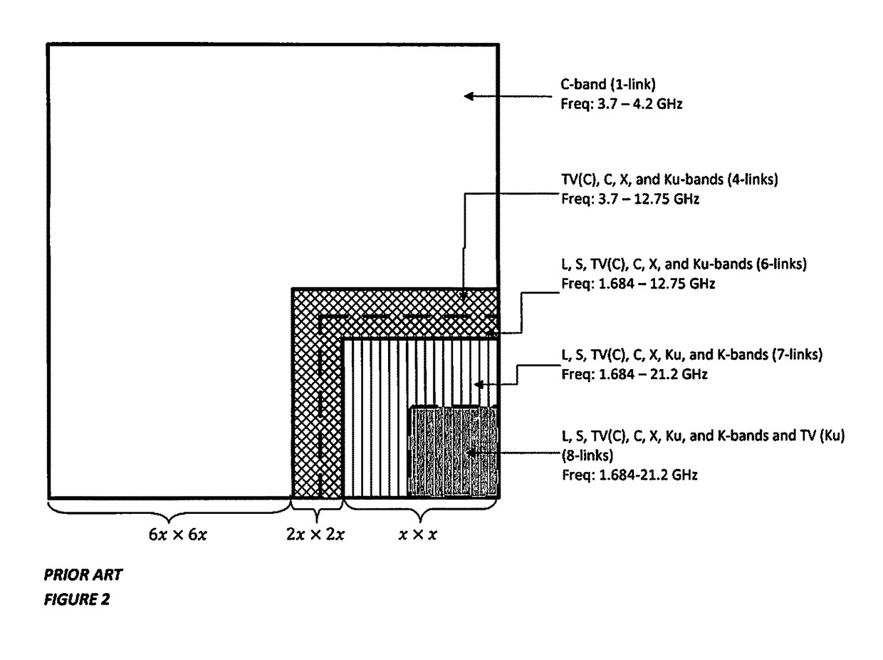
[0040]As discussed above and referring again to FIG. 2, a prior art architecture with the frequency scaled inter-element spacings, which reduces the number of elements, e.g. from 510,000 to only 116,110, but has the above-mentioned problems associated with that approach. As is discussed below, the invention overcomes these limitations, wh...


PUM


Abstract

A wideband multi-function phased array antenna aperture includes a plurality of low and high frequency phased array apertures that are asymmetrically dispersed over a largest aperture. Each aperture of the plurality of low and high frequency phased array apertures includes a plurality of frequency scaled radiating elements. The antenna aperture consolidates many functions into a single wideband multi-function phased array antenna where the use of frequency scaled elements reduces the total number of elements needed, thereby reducing the size, weight, power, cost and radar cross section when compared to conventional wideband phased array architectures.

Description

CROSS-REFERENCE TO RELATED APPLICATIONS[0001]This application claims the benefit of U.S. Provisional Application 61 / 597,859 filed on Feb. 13, 2012 and incorporated herein by reference.FIELD OF THE INVENTION[0002]The invention is directed to a phased array antenna, and in particular to a wideband multi-function phased array antenna aperture.BACKGROUND OF THE INVENTION[0003]Currently Navy ships employ a separate antenna for each function resulting in a proliferation of a large number of antennas on the ships to meet the numerous functional requirements. Recently, there is a significant interest to develop multi-function arrays using a single wideband antenna aperture, e.g. as described in G. Tavik, J. Alter, S. Brockett, M. Campbell, J. DeGraff, J. B. Evins, M. Kragalott, et al, “Advanced Multifunction Radio Concept (AMRFC) Program Final Report”, NRL Memo Report, NRL / FR / 5303—07-10,144 (June 2007). However, the number of radiating elements needed to avoid grating lobes, at the highest ...

Claims


Application Information

Patent Timeline
Patent Type & Authority Patents(United States)
IPC IPC(8): H01Q21/06H01Q1/34H01Q5/42
CPCH01Q1/34H01Q5/42H01Q21/061
Inventor MITAL, RASHMIRAO, JAGANMOHAN BPATEL, DHARMESH P.TAVIK, GREGORY C
Owner THE UNITED STATES OF AMERICA AS REPRESENTED BY THE SECRETARY OF THE NAVY
Why Eureka
Try Eureka