
Attachment structure of door mirror

a technology for door mirrors and fixing structures, which is applied in the field of fixing structures of door mirrors, can solve the problems of lack of attachment strength of door mirrors, improper shutting of visible areas, and improper noise, so as to improve door strength, increase the rigidity of attachments, and improve visibility

Inactive Publication Date: 2015-04-28
MAZDA MOTOR CORP
View PDF10 Cites 3 Cited by
  • Summary
  • Abstract
  • Description
  • Claims
  • Application Information

AI Technical Summary

Benefits of technology

The present invention provides an attachment structure for a door mirror that provides better visibility, increases attachment rigidity, and improves door strength. By positioning the door mirror in the rear layout of the door and using a connecting member to indirectly connect the mirror to reinforcing members inside the door, attachment rigidity is increased. Additionally, the reinforcing members are interconnected vertically to improve safety in a side collision. The connecting member can securely transmit the load from one reinforcing member to the other, improving load transmission efficiency. In another embodiment, the reinforcing members are interconnected at a position where they are apart from each other, improving attachment rigidity and anti-vibration effects.

Problems solved by technology

That is, in the former structure, some visible area may be improperly shut off by the triangular corner portion, which is a mirror attachment portion, and a front pillar portion.
In a case in which the door mirror is provided to project outward from the door outer panel as described above, however, there is a concern that simply fixing the door mirror to the door outer panel may cause a lack of the attachment strength of the door mirror, so that noise may be improperly caused by vehicle's vibrations which occur during the vehicle traveling.
Meanwhile, some means may be necessary in order to restrain the front side door from deforming toward the inside of a vehicle compartment against a vehicle collision, particularly against a vehicle side collision in which it is difficult to ensure a sufficient stroke for impact absorption.
However, since providing such a reinforcing member may cause increase of parts number or attaching steps, thereby increase the vehicle weight, there is a room for improvement.

Method used


Image

  • Attachment structure of door mirror
  • Attachment structure of door mirror
  • Attachment structure of door mirror

Examples


Embodiment Construction

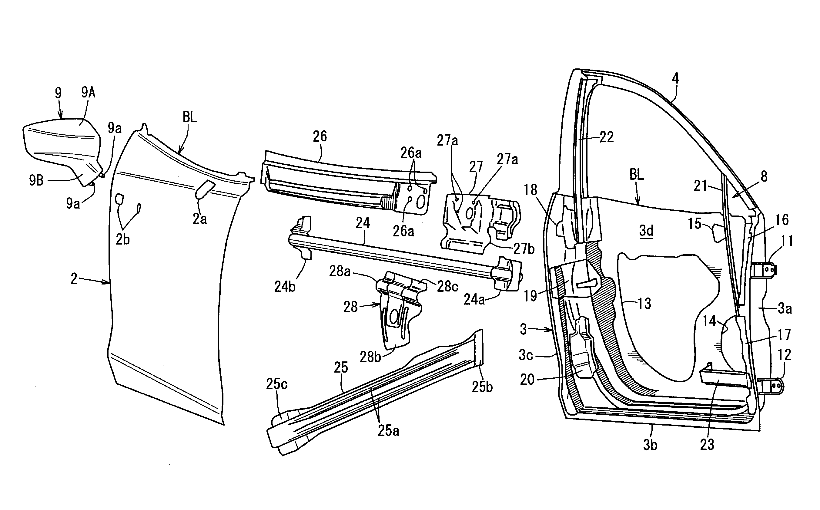
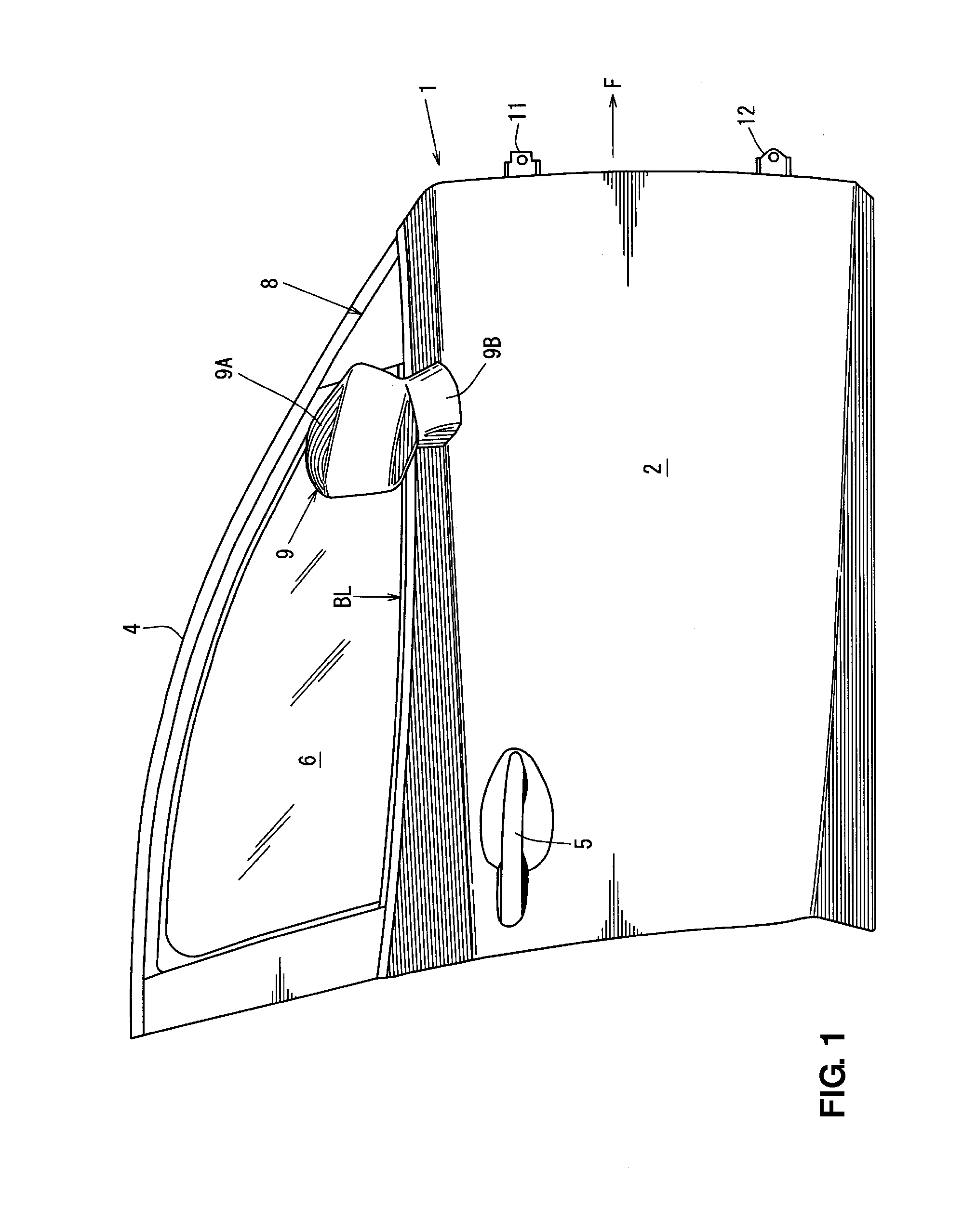
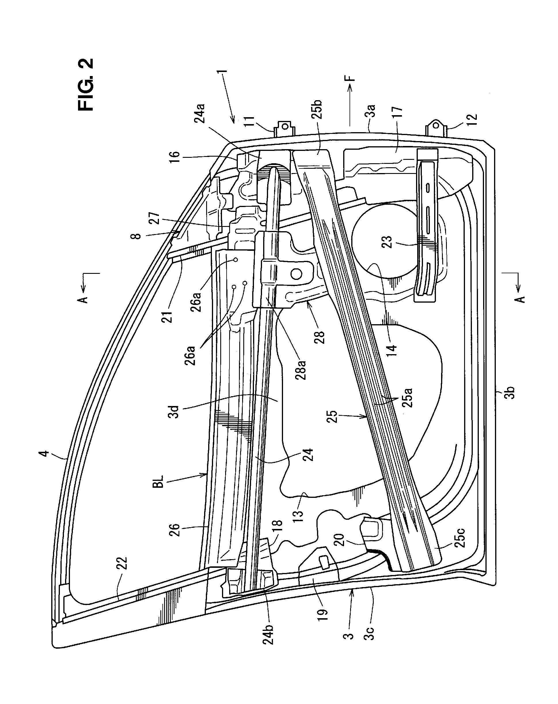
[0019]Hereinafter, a preferred embodiment of the present invention will be described specifically referring to the accompanying drawings. Figures show an attachment structure of a door mirror. FIG. 1 is a side view of a door provided on a driver's-seat side of a vehicle equipped with this attachment structure, FIG. 2 is a side view showing the door provided on the driver's-seat side of the vehicle in a state in which a door outer panel and a door mirror are removed, FIG. 3 is an exploded perspective view of the door provided on the driver's-seat side of the vehicle, FIG. 4 is a sectional view of a major portion taken along line A-A of FIG. 2, and FIG. 5 is an enlarged perspective view of the major portion in a state in which a beltline reinforcement is removed from a state shown in FIG. 2. In these figures, an arrow F shows a vehicle forward direction, an arrow R shows a vehicle rearward direction, an arrow IN shows an inward direction in a vehicle width direction, and an arrow OUT ...


PUM


Abstract

At least two reinforcing members are provided apart from each other in a vertical direction, a connecting member formed integrally with or separately from a door mirror reinforcement is provided, and the connecting member interconnects the two reinforcing members vertically at a position which is located in back of front ends of the two reinforcing members. Accordingly, the better visibility can be provided, the attachment rigidity can be increased, and the door strength can be properly improved.

Description

BACKGROUND OF THE INVENTION[0001]The present invention relates to an attachment structure of a door mirror which is attached to a door provided on a driver's-seat side of a vehicle, and specifically relates to an attachment structure of a door mirror which can ensure the attachment rigidity of the door mirror and have a sufficient strength against a vehicle side collision.[0002]Conventionally, it is known that a door mirror is provided at a so-called triangular corner portion which is formed by a beltline portion and a front pillar (a so-called A pillar) of a front side door at a front-end portion of a side window. Also, a structure in which a door mirror is provided, not at the triangular corner portion, at a position which is located in back of the triangular corner portion, projecting outward from a door outer panel is known.[0003]The structure according to the former may provide less visibility for a driver seated in a driver's seat, but the structure according to the latter can...

Claims


Application Information

Patent Timeline
Patent Type & Authority Patents(United States)
IPC IPC(8): B60J5/04B60R1/06
CPCB60J5/0404B60R1/06B60J5/0436B60J5/0429B60J5/0441B60J5/0451
Inventor KUROKI, DAISHI
Owner MAZDA MOTOR CORP
Learn More