
Optically frequency generated scanned active array

a technology of active arrays and frequency generation, applied in the field of antennas, can solve the problems of reducing the overall detection and tracking capability of the accompanying radar system, excessive signal losses, and small millimeter waves, and achieve the effect of efficient provision of the desired low noise rf signal

Inactive Publication Date: 2008-09-18
RAYTHEON CO
View PDF19 Cites 21 Cited by
  • Summary
  • Abstract
  • Description
  • Claims
  • Application Information

AI Technical Summary

Benefits of technology

This patent describes a new way to create a high quality radiofrequency (RF) signal for transmitting through an antenna. It uses a special type of light called an optical oscillator which has been designed with a specific modification. By combining this modified optical oscillator with other components like a Mach-Zender modulator, it can easily adjust the timing of different parts of the RF signal. This allows us to control how the signals are fed to the antenna, resulting in better performance without the need for expensive phase shifters at every individual element. Overall, this technology makes it possible to produce more reliable and efficient RF signals for wireless communication applications.

Problems solved by technology

The technical problem addressed in this patent text is the need for an efficient and cost-effective active array radar system that can accurately detect and track targets while avoiding the need for bulky and lossy antenna feeds and phase shifters. Additionally, there is a need for an active array radar that can be scanned in both azimuth and elevation with the same set of transmit/receive modules and without requiring conventional phase shifters.

Method used


Image

  • Optically frequency generated scanned active array
  • Optically frequency generated scanned active array
  • Optically frequency generated scanned active array

Examples


Embodiment Construction

[0023]While the present invention is described herein with reference to illustrative embodiments for particular applications, it should be understood that the invention is not limited thereto. Those having ordinary skill in the art and access to the teachings provided herein will recognize additional modifications, applications, and embodiments within the scope thereof and additional fields in which the present invention would be of significant utility.

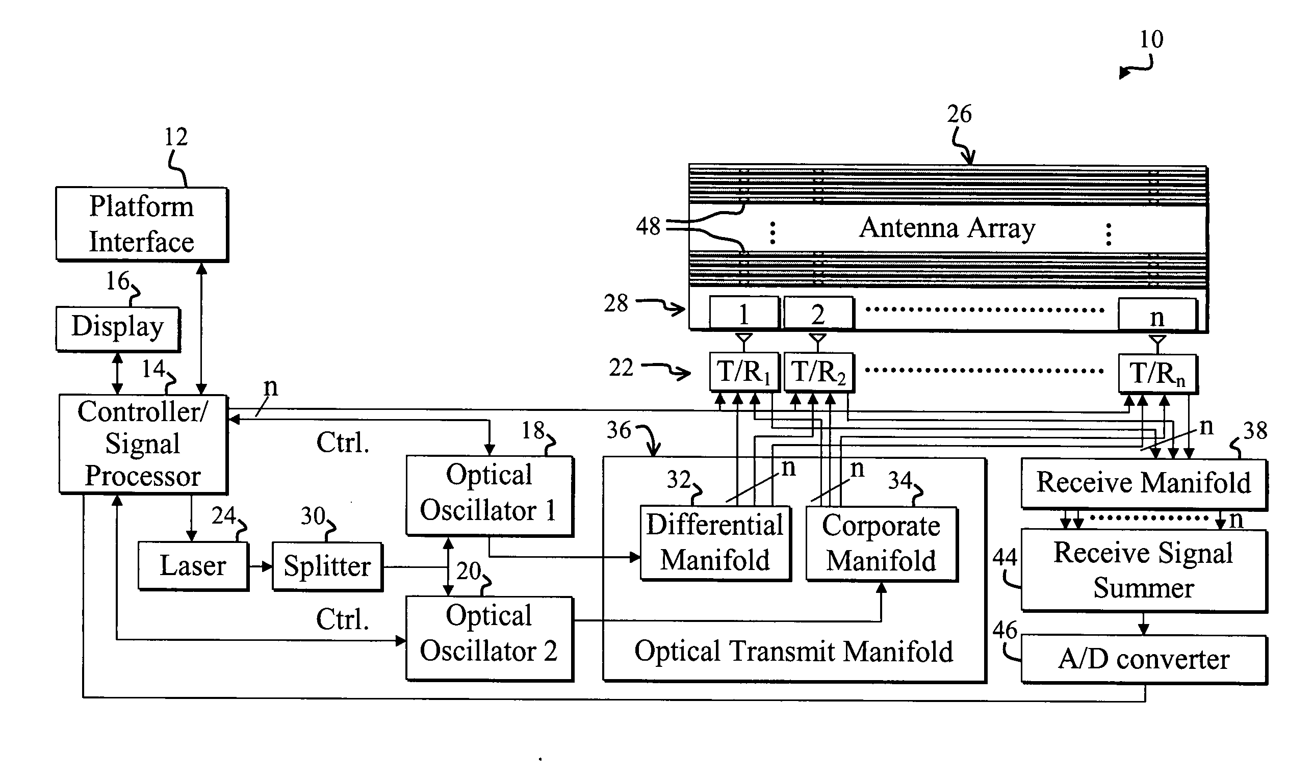
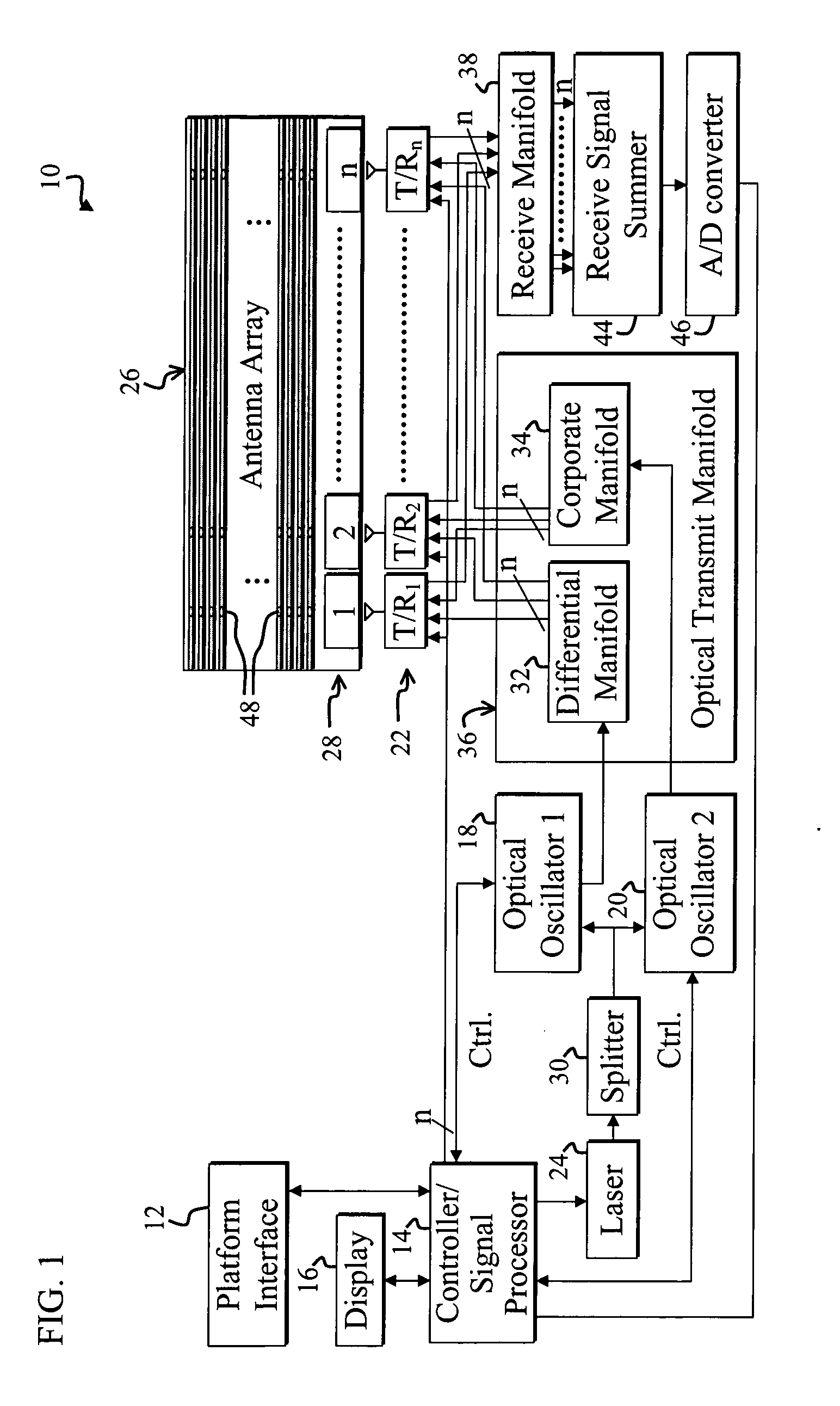
[0024]FIG. 1 is a diagram of a photonic frequency scanned active array radar system 10 that is constructed in accordance with the teachings of the present invention and that lacks phase shifters at each radiator in an accompanying array 26. For clarity, various well-known components, such as power supplies, cooling systems, and so on, have been omitted from the figures. However, those skilled in the art with access to the present teachings will know which components to implement and how to implement them to meet the needs of a given a...


PUM


Abstract

A system for scanning an antenna array of the present invention. The system includes a first mechanism for modulating a desired signal on an optical carrier signal. The first mechanism includes a frequency-tunable optical oscillator with a phase shifter for changing an output frequency of the optical oscillator. A second mechanism employs the optical carrier signal to derive signals having predetermined phase relationships. A third mechanism receives the feed signals and radiates corresponding transmit signals in response thereto to the antenna array to steer the array. In more specific embodiment, the desired signal is a Radio Frequency (RF) signal, and the phase shifter is an electrically controlled optical RF phase shifter. The optical carrier signal includes a first optical carrier signal and a second optical carrier signal. The frequency-tunable optical oscillator includes a first tunable optical oscillator for providing the first optical carrier signal and a second tunable optical oscillator for providing the second optical carrier signal. The first and second optical oscillators include first and second optical RF phase shifters, respectively, that include feedback paths having optical and electrical sections.

Description


Claims


Application Information

Patent Timeline
Owner RAYTHEON CO
Learn More