Colostomy bag

a bag and colon technology, applied in the field of colon surgery, can solve the problems of not being completely satisfactory, not eliminating the problem, and having to be removed prematurely for cleaning

Inactive Publication Date: 2008-09-18
LONGSTAFF CHARLES W
View PDF21 Cites 12 Cited by
  • Summary
  • Abstract
  • Description
  • Claims
  • Application Information

AI Technical Summary

Problems solved by technology

While these bags are generally effective to release the gases in a discreet and odourless manner, there remains the problem that the gas vent tube is placed near the top of the bag and adjacent to the stoma.
Feces entering the bag from the stoma are frequently squeezed sideways and upwardly by the pressure of the patient's belt or waistband rather than falling under gravity to the bott

Method used


Image

  • Colostomy bag
  • Colostomy bag
  • Colostomy bag

Examples


Embodiment Construction

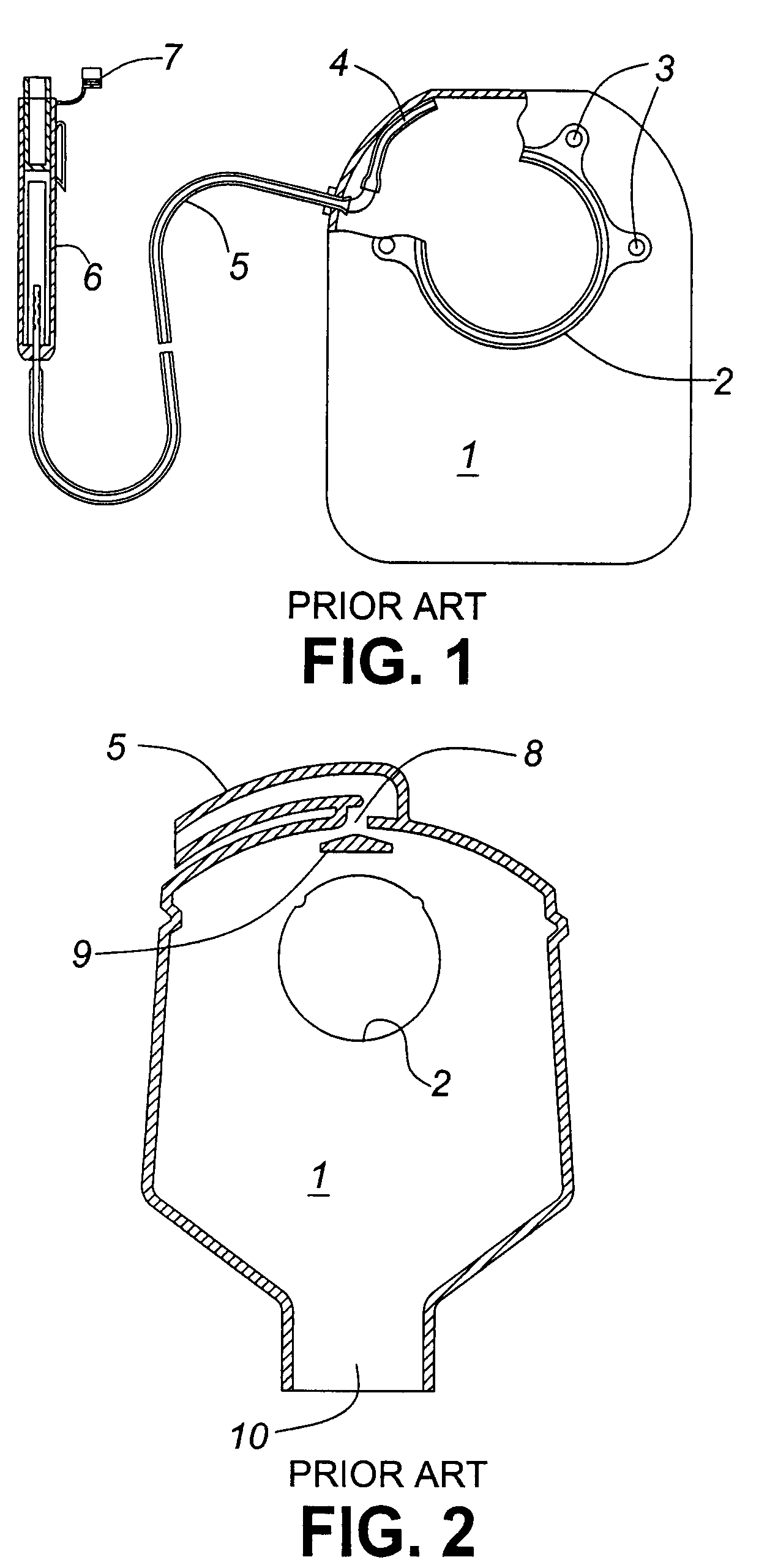
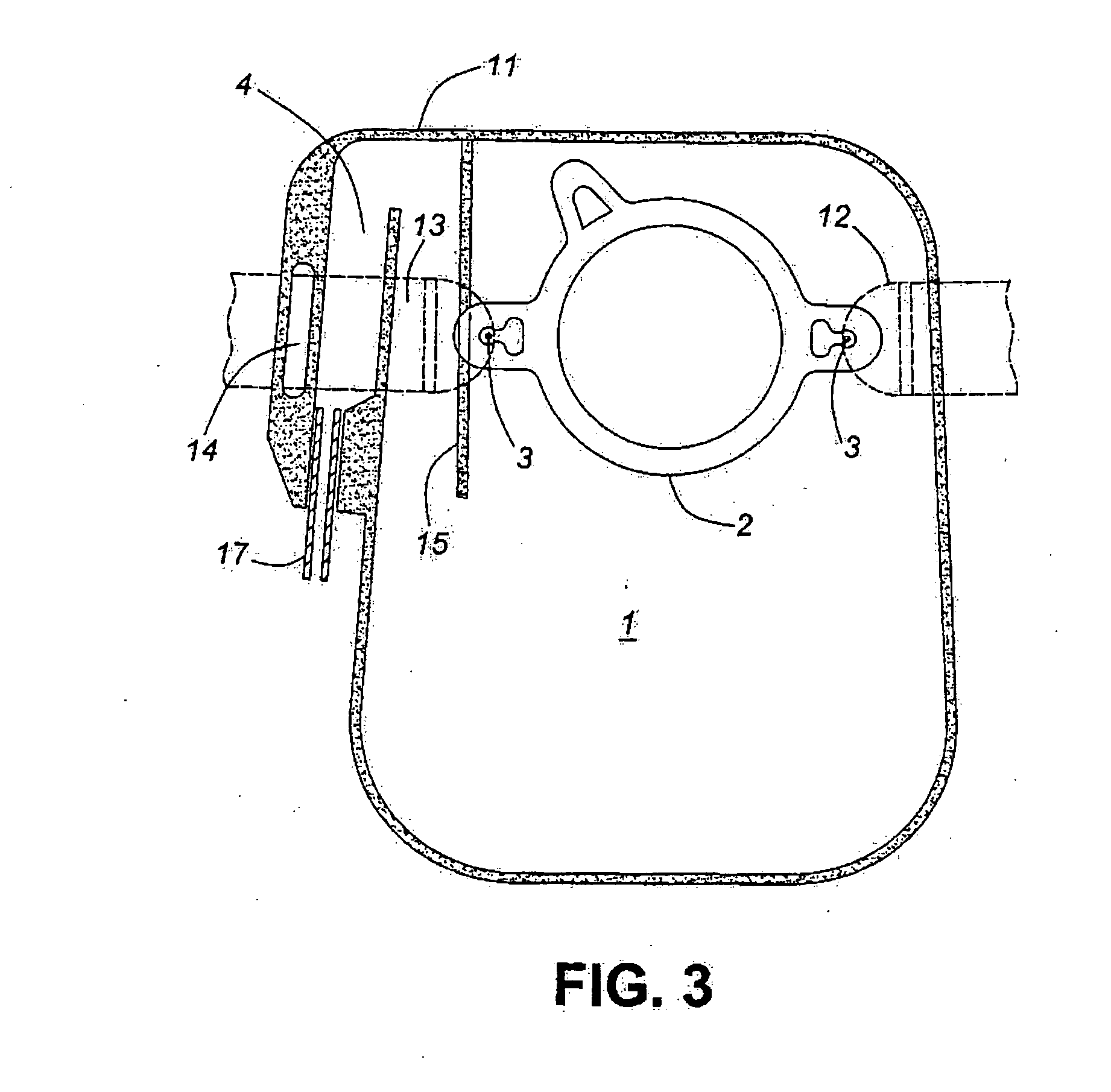
[0014]In FIG. 1 there is shown, in operative position, a typical colostomy bag 1, according to the prior art, including a stoma ring 2 for placement against the stoma in the patient's abdominal wall, belt attachment points 3, an internal vent tube 4 heat sealed adjacent an upper inner wall of the bag 1 and venting via external tube 5 to an external deodourizing filter 6, the exit of which is provided with a removable cap 7. The bag 1 is fabricated by heat sealing two planar flexible thermoplastic sheets together around the periphery of the bag. FIG. 2 shows, in operative position, a somewhat similar prior art bag 1 having a stoma ring 2, an external vent tube 5 at the top of the bag the vent opening 8 being protected by a small horizontal baffle 9 formed by heat sealing the opposing inner faces of the thermoplastic sheets from which the bag is formed in the area adjacent the vent 8. A drain 10 may be provided at the lower end of the bag to facilitate emptying thereof.
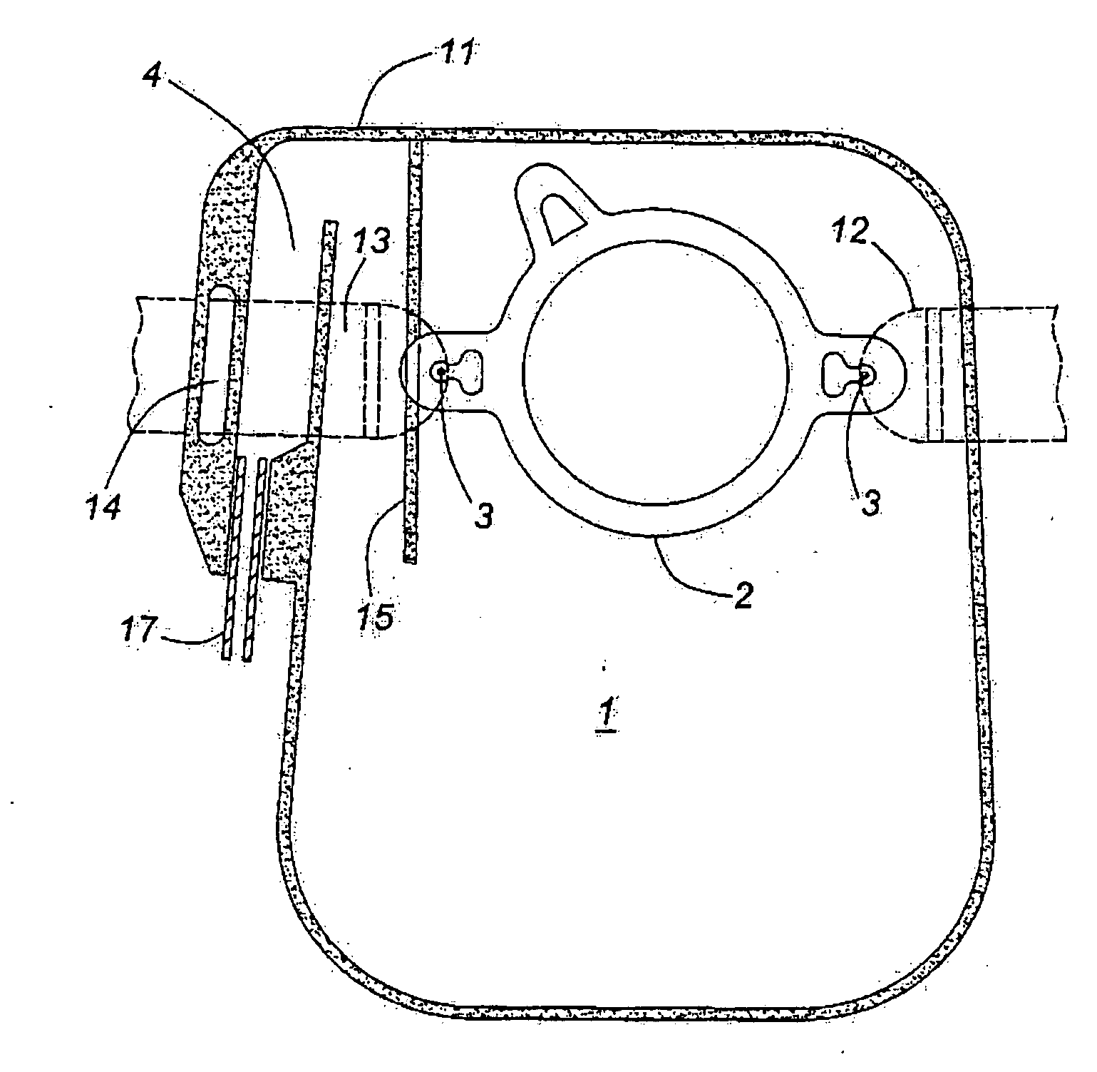
[0015]In FIG. 3...


PUM


Abstract

A colostomy bag provided with a stoma ring, a gas outlet and an external deodorizing filter in which a vertical baffle is provided intermediate the stoma ring and the gas outlet and extending from the upper marginal wall of the bag and a level slightly below the lowest point of the stoma ring. The baffle is designed to prevent feces from being squeezed sideways and upwardly into the gas outlet and clogging it.

Description

FIELD OF INVENTION[0001]This invention relates to a colostomy bag and more particularly to a colostomy bag having an external gas filter and deodorizing device.BACKGROUND OF INVENTION [0002]Colostomy is a surgical procedure to connect a patient's colon to an artificial anus, usually called a stoma, formed in the abdominal wall. Having undergone a colostomy the patient must always keep a colostomy bag in position against the stoma to receive feces and gas discharged through the stoma. An abdominal belt is usually used to hold the bag in position against the stoma immediately behind the normal beltline of a patient's clothing, where the clothing is normally tightest. In addition, the bag is normally provided with a gas vent to prevent gas build up and over inflation of the bag, and in order to eliminate offensive odours caused by the escaping gas it is common practice to provide an exterior deodorizing filter in the gas vent line. Attention is directed to U.S. Pat. No. 6,007,525 issue...

Claims


Application Information

Patent Timeline
IPC IPC(8): A61F5/44
CPCA61F5/441
Inventor LONGSTAFF, CHARLES W.
Owner LONGSTAFF CHARLES W
Why Eureka
Try Eureka