Braided Flange Branch Graft for Branch Vessel

a branch vessel and branch graft technology, applied in the field of branch vessel branch grafts, can solve the problems of limiting the range of applications in which silicone flanges with attached branch grafts could be used, and achieve the effect of small delivery profile and extremely flexibl

Inactive Publication Date: 2008-09-18
MEDTRONIC VASCULAR INC
View PDF28 Cites 21 Cited by
  • Summary
  • Abstract
  • Description
  • Claims
  • Application Information

AI Technical Summary

Benefits of technology

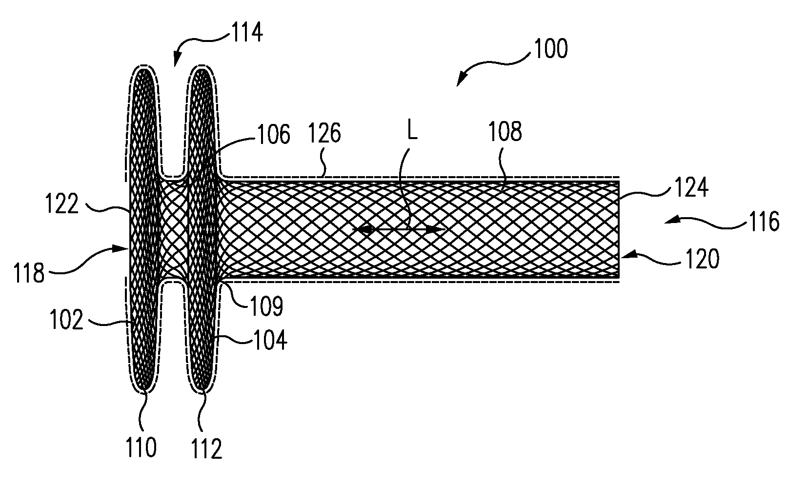
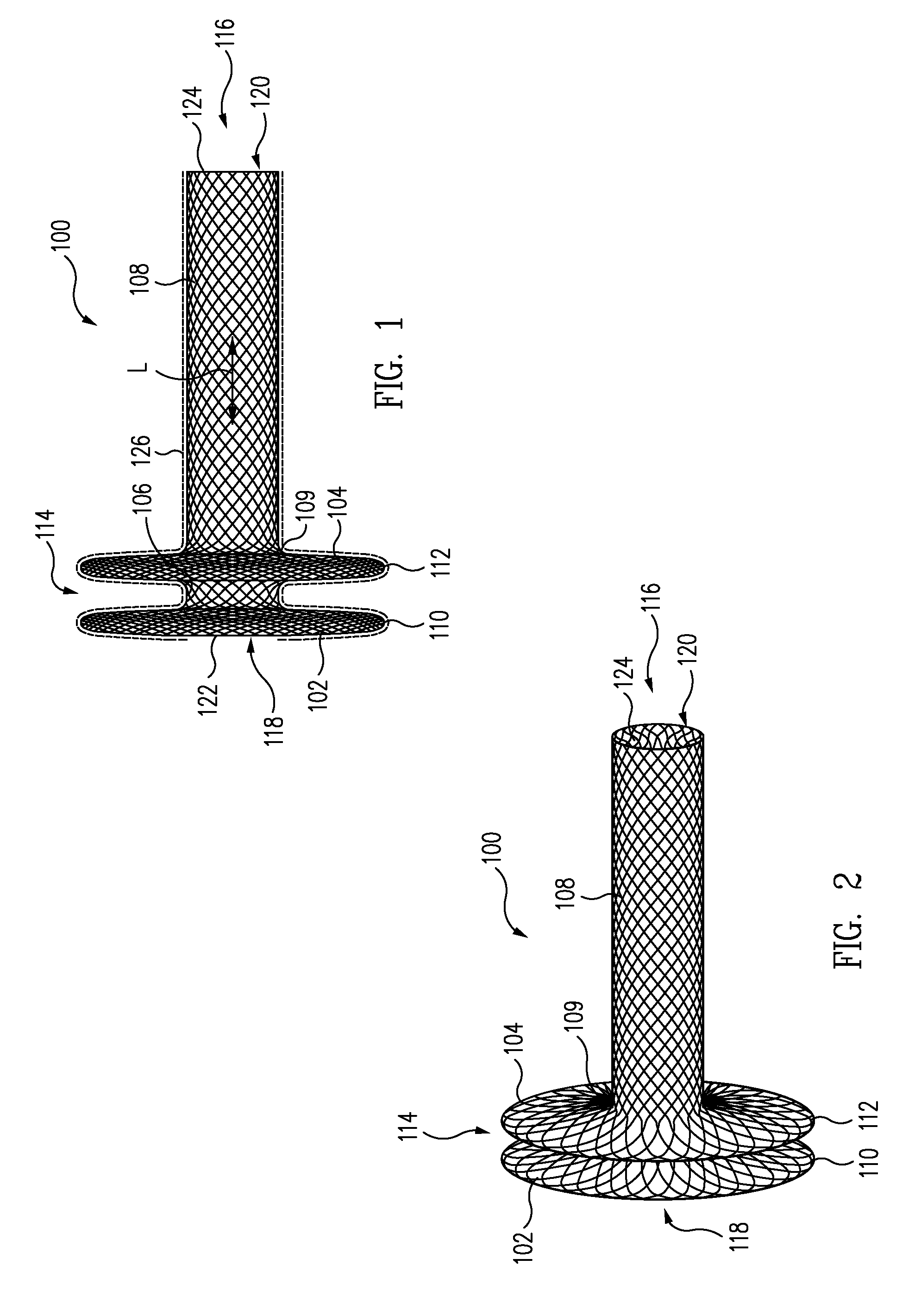
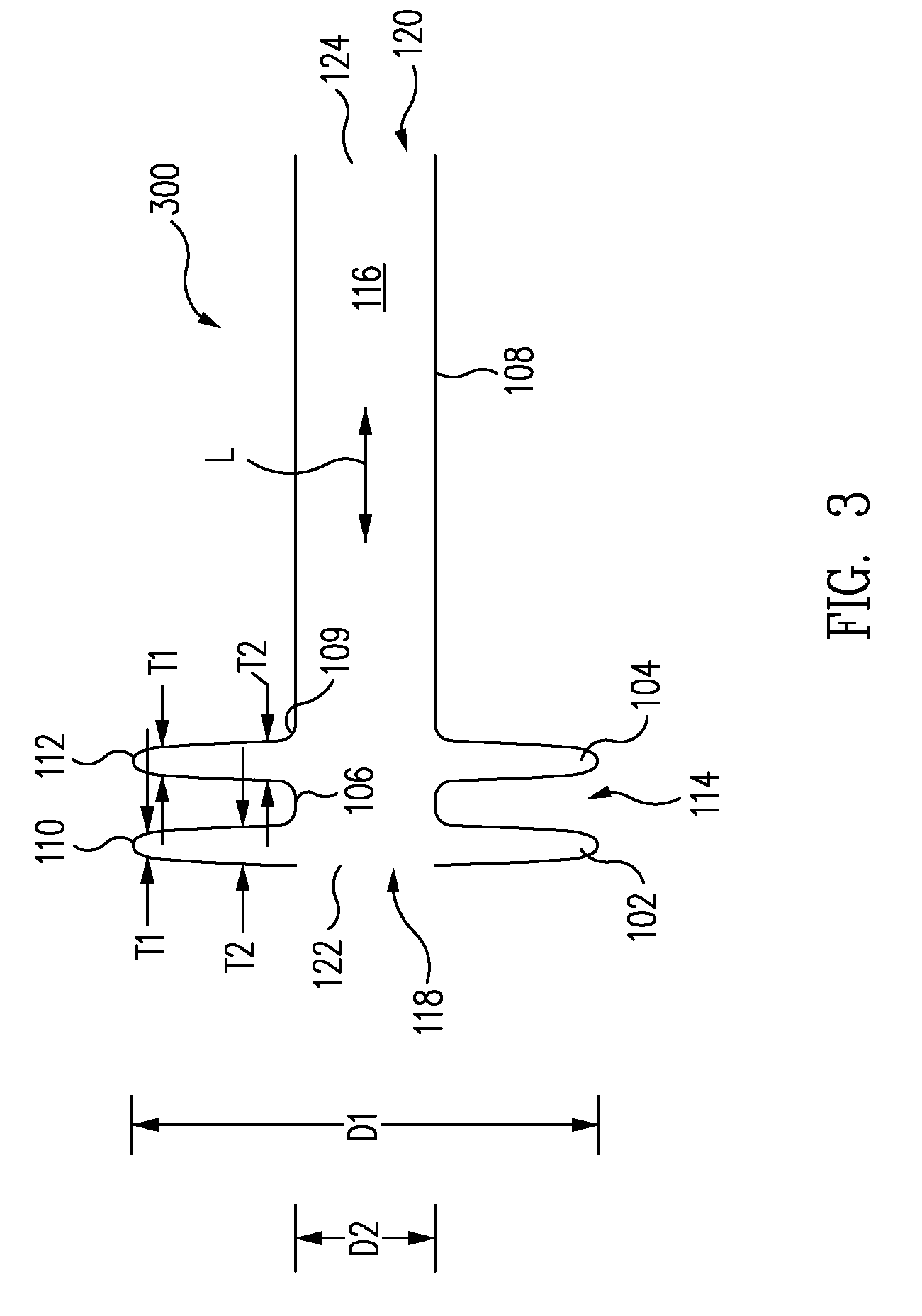
[0009]The inner flange and the outer flange have a diameter greater than a diameter of the opening in the sidewall of the main stent graft. Thus, the sidewall of the main stent graft is sandwiched between the inner flange and the outer flange securely and simply mounting the braided flange branch graft to the main stent graft. Further, when longitudinally stretched into a substantially cylindrical shape for delivery, the braided flange branch graft has a small delivery profile and is extremely flexible.

Problems solved by technology

However, the silicone flange had a relatively large delivery profile and was somewhat inflexible thus limiting the range of applications in which the silicone flange with attached branch grafts could be used.

Method used


Image

  • Braided Flange Branch Graft for Branch Vessel
  • Braided Flange Branch Graft for Branch Vessel
  • Braided Flange Branch Graft for Branch Vessel

Examples


Embodiment Construction

[0018]In accordance with one example, referring to FIG. 7, a braided flange branch graft 100 formed of a braided super elastic memory material (e.g., nitinol) includes a neck 106 between an inner flange 102 and an outer flange 104. Neck 106 is positioned in a side opening 506 in a sidewall 508 of a main stent graft 502 and inner flange 102 and outer flange 104 are deployed on opposite sides of sidewall 508. Inner flange 102 and outer flange 104 have a diameter D1 greater than a diameter D3 of side opening 506. Thus, sidewall 508 of main stent graft 502 is sandwiched between inner flange 102 and outer flange 104 securely and simply mounting braided flange branch graft 100 to main stent graft 502. Further, referring to FIG. 5, when stretched into a substantially cylindrical shape for delivery, braided flange branch graft 100 has a small delivery profile and is extremely flexible.

[0019]More particularly, FIG. 1 is a side plan view of a braided flange branch graft 100, sometimes called ...


PUM


Abstract

A braided flange branch graft formed of a braided super elastic memory material includes a neck between an inner flange and an outer flange. The neck is positioned in a side opening in a sidewall of a main stent graft and the inner flange and outer flange are deployed on opposite sides of the sidewall. The inner flange and the outer flange have a diameter greater than a diameter of the side opening in the sidewall of the main stent graft. Thus, the sidewall of the main stent graft is sandwiched between the inner flange and the outer flange securely and simply mounting the braided flange branch graft to the main stent graft. The braided flange has a substantially unobstructed fluid communication passage therethrough. Further, when stretched into a substantially cylindrical shape for delivery, the braided flange branch graft has a small delivery profile and is extremely flexible.

Description

BACKGROUND OF THE INVENTION[0001]1. Field of the Invention[0002]The present invention relates to an intra-vascular device and method. More particularly, the present invention relates to a device used to treat aneurysms where a branch connection from a main stent graft crosses the ostium of a branch vessel.[0003]2. Description of Related Art[0004]A conventional main stent graft typically includes a radially expandable reinforcement structure, formed from a plurality of annular stent rings, and a cylindrically shaped layer of graft material defining a lumen to which the stent rings are coupled. Main stent grafts are well known for use in tubular shaped human vascular or other body vessel.[0005]Endovascular aneurysmal exclusion is a method of using a main stent graft to partially or completely isolate an aneurysmal sac from systemic blood pressure by preventing pressurized blood flow from pressurizing the interior of an aneurysm, thereby reducing the risk of rupture of the aneurysm and...

Claims


Application Information

Patent Timeline
Patent Type & Authority Applications(United States)
IPC IPC(8): A61F2/06A61F2/82A61F2/90
CPCA61F2/064A61F2/07A61F2250/0039A61F2002/061A61F2002/821A61F2/90D04C1/06D10B2509/06
Inventor ERICKSON, DAVIDRAFIEE, NASSERDOUK, NAREAKMORRIS, JONATHANHANSON, CURTISRUST, MATTHEWYAMASAKI, SONNYGANESAN, PREMA
Owner MEDTRONIC VASCULAR INC
Why Eureka
Try Eureka