One piece loop and coil

Inactive Publication Date: 2008-01-22
BOSTON SCI SCIMED INC
View PDF320 Cites 21 Cited by
  • Summary
  • Abstract
  • Description
  • Claims
  • Application Information

AI Technical Summary

Benefits of technology

[0015]It is an object of the present invention to provide a reliable vascular filter that is capable of being fully deployed in tortuous anatomy.
[0016]It is another object of this invention to provide a vascular filter that is capable of spanning a range of vessel sizes, thereby reducing inventory requirements.
[0020]It is a further object of the present invention to provide a vascular device that is capable of being contracted to a small delivery profile, thus permitting use of the device in vessels having relatively small diameters.
[0024]In alternative embodiments, the one or more suspension strut may further consist coils formed to enhance apposition of the support hoop to the vessel walls, or a nose cone mounted on the support tube. As a further alternative, the suspension strut may be configured as series of loops or coil turns in the guide wire proximal to the point of attachment of the support hoop, thereby isolating the filter from lateral or torsional disturbances applied at the proximal end of the guide wire. In still other alternative embodiments, sac bunching may be mitigated by tapering the sac or attaching it to the support tube.

Problems solved by technology

This dislodged material, known as emboli, enters the bloodstream, and may be large enough to occlude smaller downstream vessels, potentially blocking blood flow to tissue.
The resulting ischemia poses a serious threat to the health or life of a patient if the blockage occurs in critical tissue, such as the heart, lungs, or brain.
The deployment of stents and stent-grafts to treat vascular disease, such as aneurysms, also involves introduction of foreign objects into the bloodstream, and also may result in the formation of clots or release of emboli.
Such particulate matter, if released into the bloodstream, also may cause infarction or stroke.
Furthermore, interventional procedures may generate foreign bodies that are left within a patient's bloodstream, thereby endangering the life of the patient.
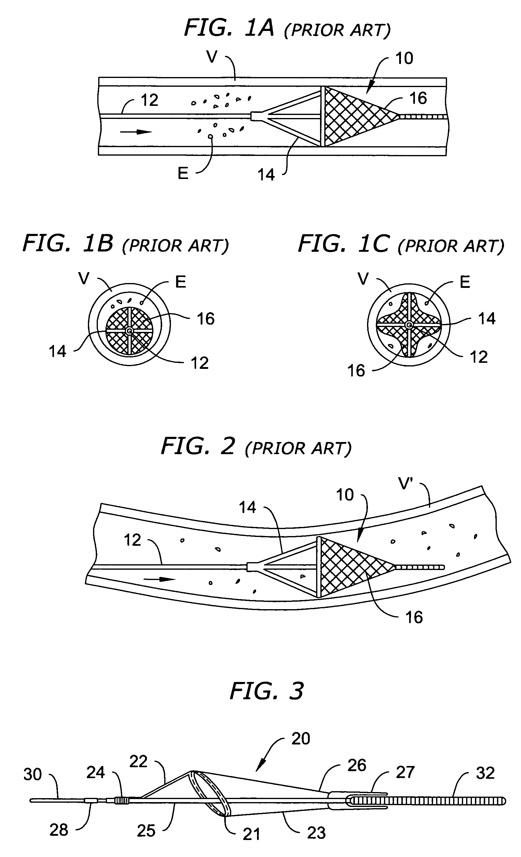
A drawback of such previously known systems, however, is that occlusion of antegrade flow through the vessel may result in damage to the tissue normally fed by the blocked vessel.
One disadvantage of radially expandable filter systems such as described in the foregoing patents is the relative complexity of the devices, which typically include several parts.
Connecting more than a minimal number of such parts to a guide wire generally increases delivery complications.
Consequently, it may be difficult or impossible to use such devices in small diameter vessels, such as are commonly found in the carotid artery and cerebral vasculature.
Moreover, such filter devices are generally incapable of preventing material from escaping from the filter during the process of collapsing the filter for removal.
One disadvantage of such systems is that the filters have only a limited range of operating sizes.
Still further, such filters generally do not maintain apposition to the vessel wall when blood pressure pulses pass along a vessel, e.g., due to systole.
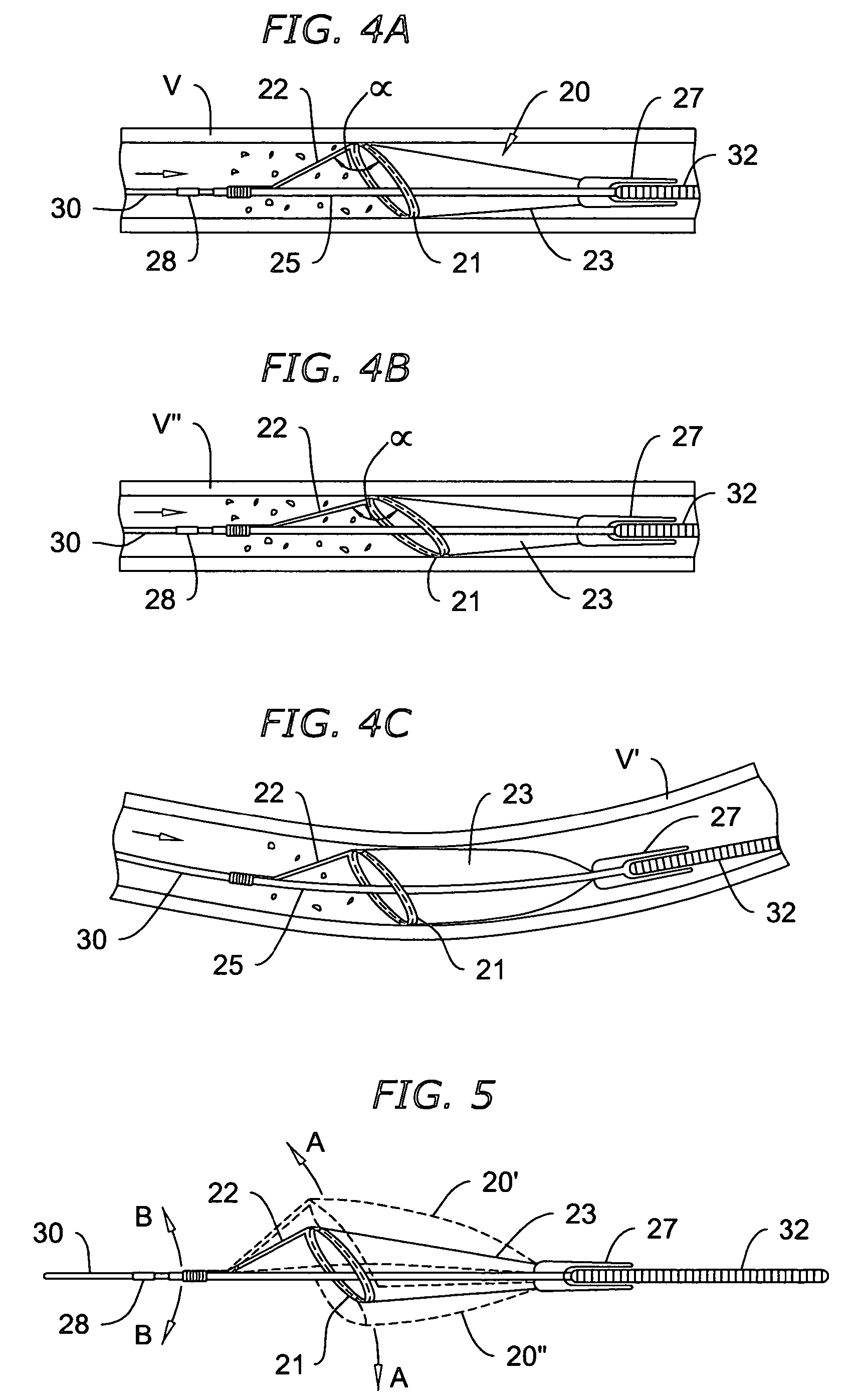
In this case, because a blood pressure pulse can cause local swelling of the vessel diameter, the pressure pulse can cause the vessel to momentarily become lifted off the perimeter of the filter, thereby permitting emboli to bypass the filter.
While the 
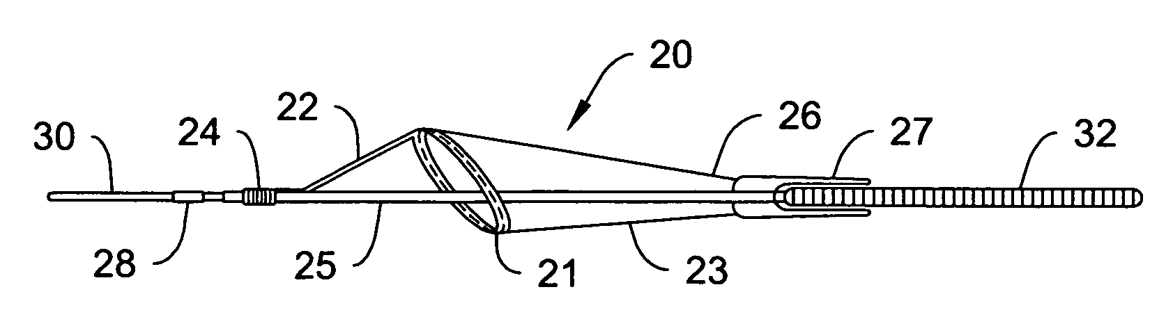
filter system described in the foregoing International Publication reduces the number of components used to deploy the cone-shaped basket, as compared to the umbrella-type filter elements described hereinabove, it too has drawbacks.
One such drawback is that because the hoop is fixed directly to the guide wire, the cone-shaped basket may not be fully deployable in a tortuous vessel.
This problem is expected to arise, for example, where the resistance of the elongated member to bend to accommodate the tortuosity of the vessel causes the hoop and basket to be lifted away from the vessel wall, thereby providing a path for emboli-laden blood to bypass the filter.
Moreover, because the hoop in the aforementioned reference is directly fastened to the elongated member, there is also a risk that the basket will collapse or become wound around the elongated member due to twisting of the elongated member, e.g., during transluminal insertion of the filter, or during manipulation of the proximal end of the elongated member during insertion or withdrawal of interventional devices along the elongated member.
Furthermore, the method for flexibly attaching the filter hoop to the elongated member poses additional challenges.
As discussed in the foregoing, if the filter is rigidly affixed directly to the elongated member, then the maneuverability required in accommodating tortuous vessels is compromised.
Also, if the filter assembly is not properly attached to the elongated member, then the filter may become disengaged, thereby posing additional risks.

Method used


Image

  • One piece loop and coil
  • One piece loop and coil
  • One piece loop and coil

Examples


Embodiment Construction

[0042]The above and other objects and advantages of the present invention will be apparent upon consideration of the following detailed description, taken in conjunction with the accompanying drawings, in which like reference characters refer to like parts throughout, and in which:

[0043]Referring to FIGS. 1A-1C and 2, some of the disadvantages of previously known umbrella-type filters are described as context for the benefits achievable with the vascular filter of the present invention. FIG. 1A shows a previously known umbrella-type filter 10 deployed in a straight length of vessel V, with emboli E approaching with antegrade flow. Filter 10 is disposed on guide wire 12 and includes one or more radially extending suspension strut 14 supporting biocompatible mesh 16.

[0044]FIG. 1B illustrates a situation that may arise wherein the clinician underestimates the diameter of vessel V and deploys an undersized vascular filter 10. Because umbrella-type filters generally are capable of spanni...


PUM


Abstract

Apparatus and methods are provided for use in filtering emboli from a vessel, wherein a vascular filter is disposed on a guide wire, the vascular filter having a support hoop disposed from a suspension strut so as to permit lateral eccentric displacement of the support hoop relative to a longitudinal axis of the guide wire. A blood permeable sac is affixed to the support hoop to form a mouth of the blood permeable sac. The support hoop is disposed obliquely relative to the guide wire and is capable of being properly used in a wide range of vessel diameters. The support hoop collapses the mouth of the blood permeable sac during removal of the vascular filter to prevent material from escaping from the sac. A delivery sheath and introducer sheath for use with the vascular filter of the present invention are also provided.

Description

REFERENCE TO RELATED APPLICATIONS[0001]This application is a continuation-in-part of U.S. patent application Ser. No. 09 / 764,774 filed Jan. 16, 2001, now abandoned; which is in turn a continuation-in-part of U.S. patent application Ser. No. 09 / 430,211 filed Oct. 29, 1999, now U.S. Pat. No. 6,589,263; which is a continuation-in-part of U.S. patent application Ser. No. 09 / 364,064 filed Jul. 30, 1999, now U.S. Pat. No. 6,530,939.FIELD OF THE INVENTION[0002]The present invention relates to apparatus and methods for filtering or removing matter from within a vascular system. More particularly, the present invention provides a low profile self-expanding vascular device useful for capturing emboli or foreign bodies generated during interventional procedures.BACKGROUND OF THE INVENTION[0003]Percutaneous interventional procedures to treat occlusive vascular disease, such as angioplasty, atherectomy and stenting, often dislodge material from the vessel walls. This dislodged material, known as...

Claims


Application Information

Patent Timeline
IPC IPC(8): A61M29/00A61F2/06A61B17/22A61F2/01
CPCA61B17/221A61F2/01A61F2/013A61B2017/2215A61F2002/011A61F2002/015A61M2025/09183A61M2025/1052A61M2025/109A61F2002/018A61F2230/0008A61F2230/0067A61F2230/008A61F2/011A61F2/0105
Inventor DEMOND, JACKSONMORENO, MARLON C.CASSELL, ROBERT L.HIRSHMAN, PETERKIM, ELIOT T.
Owner BOSTON SCI SCIMED INC
Why Eureka
Try Eureka