
Method and system for enhanced cursor control

a cursor control and cursor technology, applied in the field of computer hardware, can solve the problems of discomfort and injury, moving the cursor quickly, efficiently, and moving the cursor, and achieve the effect of shortening and speeding up

Inactive Publication Date: 2008-09-18
WARNER ERVIN DAWSON
View PDF32 Cites 101 Cited by
  • Summary
  • Abstract
  • Description
  • Claims
  • Application Information

AI Technical Summary

Benefits of technology

"The invention is a software program that displays virtual cursors on a computer screen, allowing the user to quickly and easily position the cursor to a specific point on the screen. The software program uses information about the user's actions and the position of the cursor to determine the intended destination and then moves the cursor to that position. This saves time and makes the process faster. The software program can also display a series of virtual cursors based on the user's previous actions, making it easier to quickly move between different positions on the screen. Overall, the invention improves the efficiency and ease of use of computer software."

Problems solved by technology

Currently, there are various problems associated with moving a cursor on a computer screen using a mouse or other similar peripheral device.
There is a problem of moving a cursor quickly, efficiently, and accurately on displays with increasingly higher resolutions.
There is also a problem of moving a cursor when the motion and range of the input device (mouse, keyboard, joystick, trackpad™, trackpoint™, etc.) is constrained.
Finally, there is the problem of large repetitive motions when using a input device to move the cursor on computer displays which can cause discomfort and injury.

Method used


Image

  • Method and system for enhanced cursor control
  • Method and system for enhanced cursor control
  • Method and system for enhanced cursor control

Examples


example 1

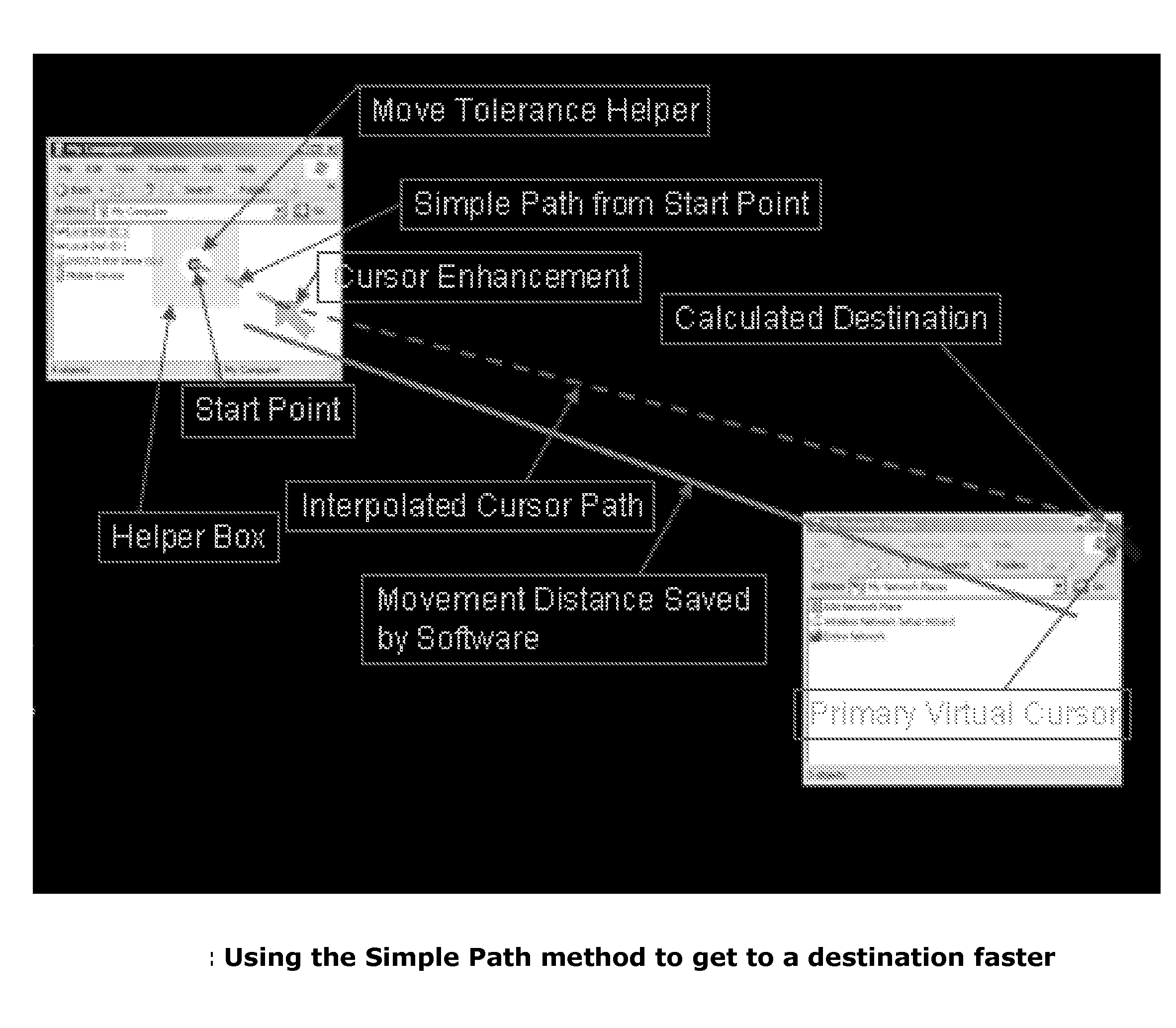
[0168]Referring now to FIG. 8, which shows using the Simple Path method to get to a destination faster—In this example, the user is trying to get to a point on the far-right side of the screen relative to the position of the actual cursor—start point. Because the user has enabled the enhance cursor feature, the software has highlighted the cursor with a green cursor enhancement arrow. After the user moves the cursor from the start point, the software displays a helper box (general area that the software is actively calculating the intended cursor destination) and calculates the path and distance using a simple path method described above. After the user has moved the cursor outside of the minimum move distance (visible within the helper box ), the software displays the virtual cursor at the calculated intended cursor destination. The user can then use the selected software activation input to quickly reposition the actual cursor at the intended cursor destination that the software h...

example 2

[0169]Referring now to FIG. 9, which shows using the Complex Path method to get to a destination faster—This example is similar to Example 1 except the diagram has been updated to reflect the complex direction and distance calculation processes of the software. In addition to the enhanced cursor, helper window, and virtual cursor, an example path that the software has interpolated is highlighted.

example 3

[0170]Referring now to FIG. 10, which shows using the Virtual Screen method to get to a destination faster—This example is similar to example 1 except the diagram has been updated to reflect the virtual screen method calculation process of the software. It highlights the differences in the function of the helper box, specifically how it maps a relative position in the virtual screen to an actual position on the actual display.


PUM


Abstract

Methods and systems for moving a cursor quickly, efficiently, and accurately on displays with increasingly higher resolutions, for moving a cursor when the motion and range of the input device (mouse, keyboard, joystick, trackpad™, trackpoint™, etc.) is constrained, and for avoiding the problem of large repetitive motions when using an input device to move the cursor on computer displays.

Description

PRIORITY CLAIM[0001]This application claims benefit under 35 USC 119(e) of the filing date of U.S. provisional No. 60 / 785,272 filed 24 Mar. 2006 and also of U.S. provisional No. 60 / 789,916 filed 7 Apr. 2006.BACKGROUND[0002]1. Field of the Invention[0003]The invention relates to computer hardware and associated software, and in particular, a standard computer peripheral, e.g. a mouse, for controlling the cursor, and predictive software that improves functionality.[0004]2. Description of the Prior Art[0005]Currently, there are various problems associated with moving a cursor on a computer screen using a mouse or other similar peripheral device. There is a problem of moving a cursor quickly, efficiently, and accurately on displays with increasingly higher resolutions. There is also a problem of moving a cursor when the motion and range of the input device (mouse, keyboard, joystick, trackpad™, trackpoint™, etc.) is constrained. Finally, there is the problem of large repetitive motions ...

Claims


Application Information

Patent Timeline
Patent Type & Authority Applications(United States)
IPC IPC(8): G06F3/048
CPCG06F3/04812
Inventor WARNER, ERVIN-DAWSON
Owner WARNER ERVIN DAWSON
Learn More