Mounting Plate for Electronic Components

Inactive Publication Date: 2008-09-25
RITTALWERK RUDOLF LOH GMBH & CO KG
View PDF10 Cites 19 Cited by
  • Summary
  • Abstract
  • Description
  • Claims
  • Application Information

AI Technical Summary

Benefits of technology

[0023]An intended arrangement at practically any desired location of the mounting level without additional bores is possible if at least one strip-like bridge is provided, which can be displaceably inserted at a distance from the mounting level between two holding strips arranged on both sides of a component parallel with respect to each other, and has bores, by which the component can be fixed in place at its base by at least one attachment screw.
[0024]Here, those steps contribute to simple mounting, w

Problems solved by technology

Because of the cooling coils, however, holes cannot be drilled without danger of damage to the known mounting plates.
Thus, it is often not possible to provide the mounting plate with a predetermined grid of threaded holes, because the threaded holes applied to the housings of the electronic components are not alig

Method used


Image

  • Mounting Plate for Electronic Components
  • Mounting Plate for Electronic Components
  • Mounting Plate for Electronic Components

Examples


Example

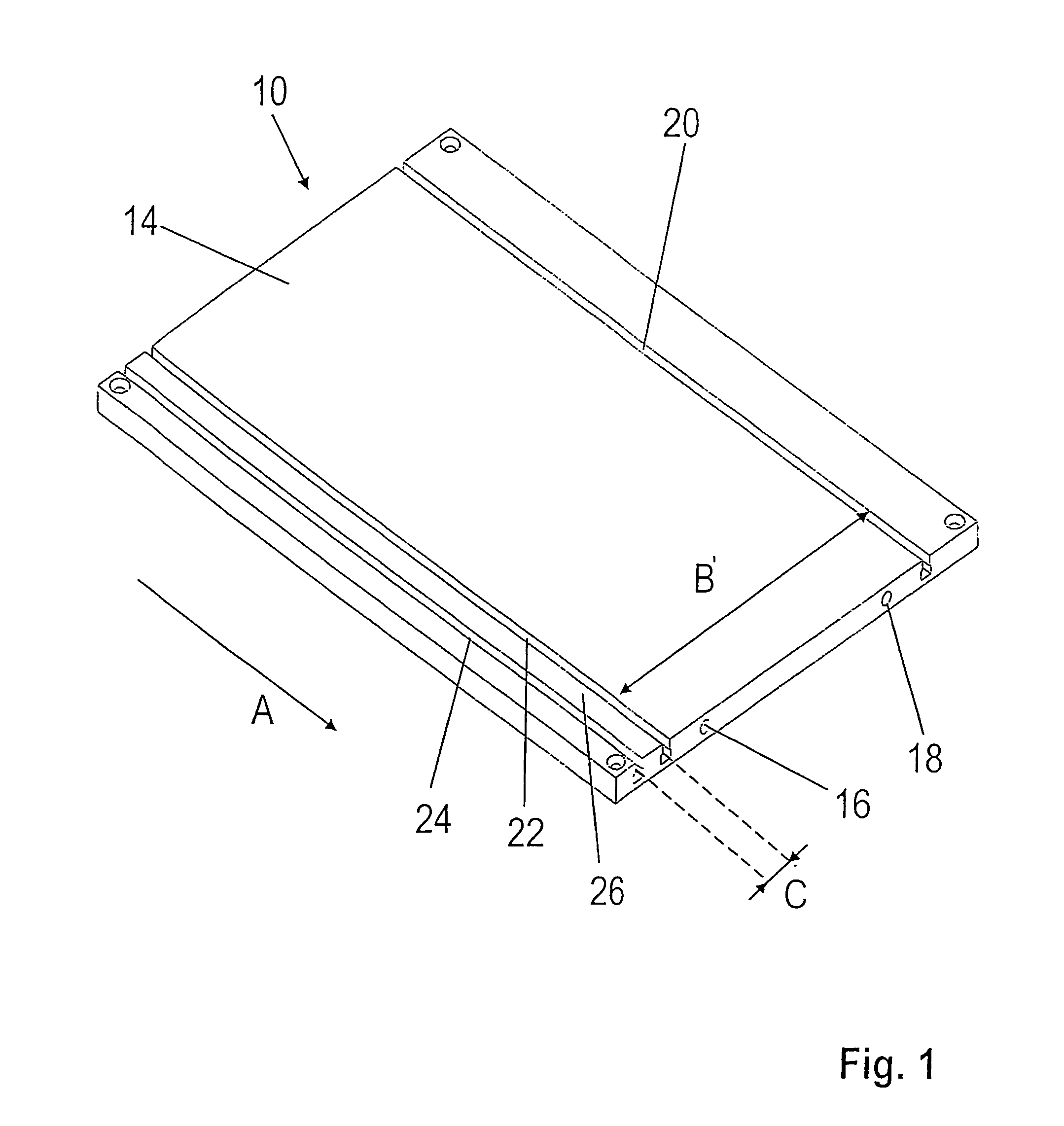
[0035]In a schematic and perspective lateral view, FIG. 1 shows a mounting plate 10 without electronic components which are to be mounted on it and to be cooled. The mounting plate 10 has a flat plate body 14 made, for example, of aluminum, in which a cooling circuit is embodied with connectors 16 and 18 in the form of a cooling coil, not shown, for the flow-through of a cooling fluid. In the area in which the cooling fluid coil is integrally deployed, the plate body 14 is not additionally processed, but instead is designed flat and level. On the side to the right in FIG. 1, of the area in which the cooling fluid coil is integrally placed, an undercut first groove 20 is formed in one piece with the plate body, which is approximately C-shaped in cross section and extends in a straight line in the direction (arrow A) of extension of the mounting plate 14. At least one holding element, for example a spring nut (not represented), a sliding block 25 (FIG. 4a), and / or a groove insert (FIG...


PUM


Abstract

A mounting plate for electronic components, including cooling conduits that are integrated into a plate body and that are traversed by a coolant, and a fixing device for mounting the electronic components being located on the plate body. The fixing device includes at least one retaining piece and a first recessed groove or channel that extends in a linear manner in the direction of extension of the mounting plate. A retaining piece, which includes a fixing thread, for securing the component can be inserted into the groove or channel.

Description

BACKGROUND OF THE INVENTION[0001]1. Field of the Invention[0002]This invention relates to a mounting plate for electronic components, in particular with cooling conduits integrated in a plate body for a cooling medium to flow through, wherein a fastening arrangement for mounting the electronic components is arranged on the plate body.[0003]2. Discussion of Related Art[0004]It is known to insert cooling coils into a mounting plate or mounting board made of aluminum, in order to cool electronic devices, for example frequency converters, to be mounted on the mounting plate. The waste heat from the electronic components can be carried off by such a “cold plate”.[0005]The electronic components can be maintained on such a known mounting plate with screw connections. For this purpose, there are screw holes in the housings of the electronic components, through which a screw can be rotated into threaded holes to be cut into the mounting plate. Because of the cooling coils, however, holes can...

Claims


Application Information

Patent Timeline
IPC IPC(8): H05K7/20H01L23/34H01L25/07H05K5/02H05K7/14
CPCH05K7/20627H05K7/1474
Inventor LANG, MARTINREUTER, WOLFGANGBESSERER, HORSTSAVASCI, AHMET
Owner RITTALWERK RUDOLF LOH GMBH & CO KG
Why Eureka
Try Eureka