Diaphragm circulator

US20080232987A1Inactive Publication Date: 2008-09-25AMS R&D

Image

  • Diaphragm circulator
  • Diaphragm circulator
  • Diaphragm circulator

Examples


Embodiment Construction

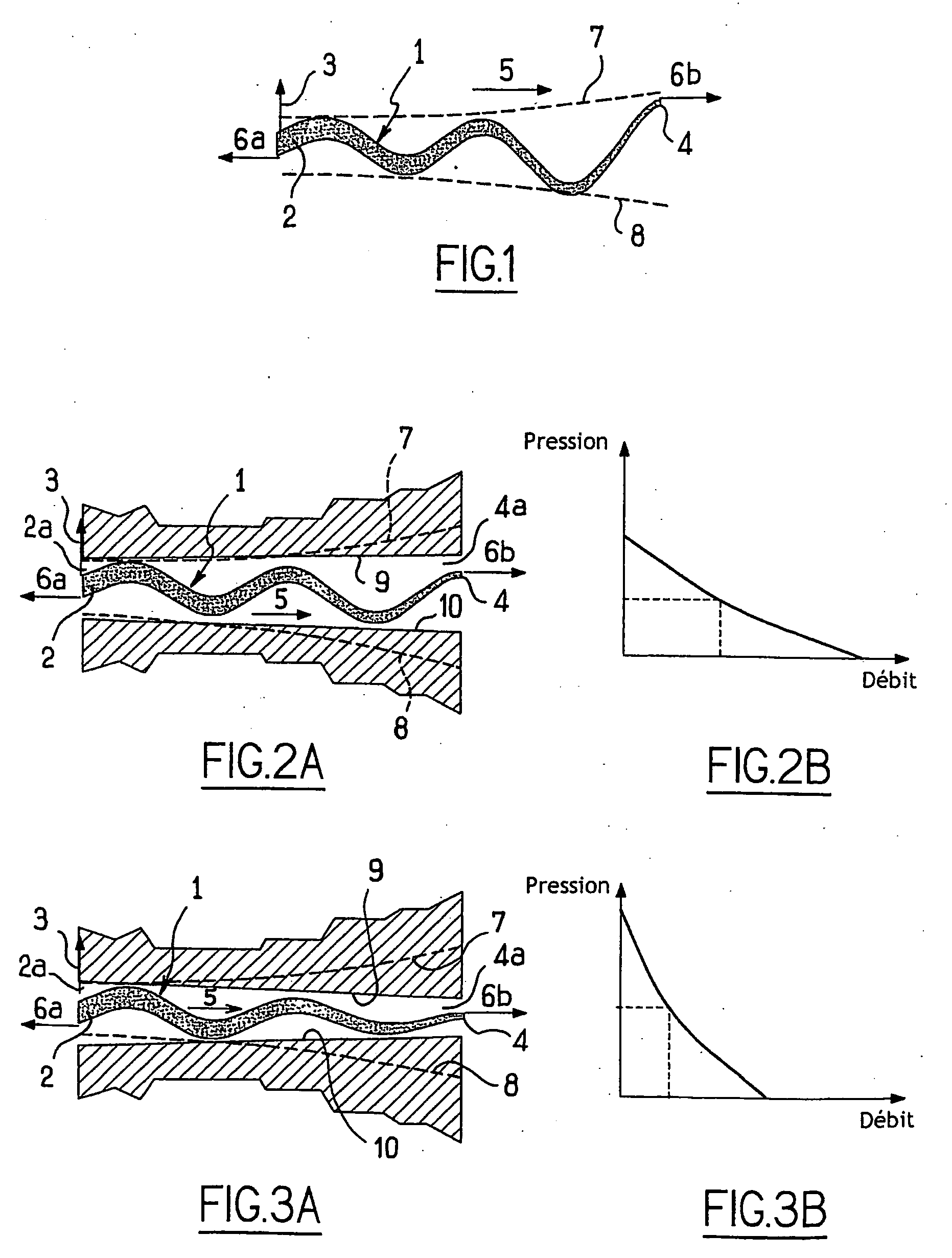
[0044]A sectional view of a diaphragm 1 has been shown in FIG. 1, having one end (or one edge) 2 subjected to a reciprocating mechanical excitation force 3 of this end 2, which is perpendicular to the plane of the diaphragm, and which is generated by an electromechanical actuator. The diaphragm comprises another edge 4, with the result being that a direction of propagation 5 is defined between the two edges, for the ripples produced by the reciprocating mechanical force 3.

[0045]The edges 2 and 4 of the diaphragm may be rectilinear or concentrically circular. Mention will also be made of tubular-shaped diaphragms each of the edges of which are at one end of a tube.

[0046]Tension in the existing diaphragm in its resting state or resulting from a resistance to its elongation under the effect of this mechanical stress is represented by the forces 6a and 6b. This diaphragm, now extended, is the source of propagation of the wave in the direction of the tension.

[0047]Assuming that edge 4 is...


PUM


Abstract

A diaphragm circulator for liquid material having an internal circuit provided with at least one material intake orifice for discharging the material. The circulator body defines a propulsion chamber with rigid walls between which a deformable diaphragm is placed in such a way that the edge thereof is adjacent to the intake oriface and the edge is adjacent to the discharge orifice for forming a ripple carrier. A diaphragm-exciting member is arranged on the side of the intake orifice for producing a reciprocating motion on the corresponding diaphragm edge in such a way that the ripple is generated and is provided with the circulator rigid walls which are arranged inside free ripple amplitude envelope surfaces extending along the diaphragm. The diaphragm is associated by at least one edge thereof with means for generating a tension therein at least while the ripple is generated in such a way that during the operation, the diaphragm tension on the side of the discharge orifice is greater than on the side of the intake orifice.

Description

BACKGROUND OF THE INVENTION[0001](1) Technical Field[0002]This invention relates to a diaphragm circulator and, more generally, to a device whereby mechanical power is converted into hydraulic power, i.e., the product of the flow rate multiplied by the pressure, for a liquid or gaseous fluid charged or uncharged with particles, or for any material capable of flowing (divided, powdery, fluidized or emulsified materials).[0003](2) Description of the Prior Art[0004]There are numerous types of pumps, suction devices, compressors, fans . . . which perform this function. A new technique has recently appeared for providing this function, at least for a liquid, by means of a diaphragm acting as an intermediate means of converting (a transfer medium) mechanical power (the integral over a time interval of the product of force multiplied by displacement) into hydraulic power (the integral over the same interval of the product of flow rate multiplied by pressure), this transfer occurring by way...

Claims


Application Information

Patent Timeline
25 Sep 2008
Publication
US20080232987A1
IPC
F04B43/08
CPC
F04B43/0018; F04B43/02; F04B43/0054; F04B43/14
Inventors
DREVET, JEAN-BAPTISTE