
No data loss system with reduced commit latency

a data loss and commit latency technology, applied in the field of data loss systems, can solve the problems of data loss, prior art's tradeoff between data protection and commit latency is not optimal, etc., and achieve the effect of reducing the time required

Active Publication Date: 2008-09-25
ORACLE INT CORP
View PDF12 Cites 28 Cited by
  • Summary
  • Abstract
  • Description
  • Claims
  • Application Information

AI Technical Summary

Benefits of technology

The invention relates to a method and system for optimizing the trade-off between data protection and commit latency in a database system. The method involves acknowledging the receipt of redo data to a primary database system and writing the data to a standby database system. The standby database system may have a log file that includes a no data loss indicator to indicate if there are gaps in the redo data stream. The system may also operate in an acknowledgement mode where the standby database system sends the acknowledgement to the primary database system before or after writing the redo data item to persistent storage. The invention also includes storage devices that contain programs and redo log files made according to the invention. The technical effects of the invention include reducing the time required to acknowledgement of redo data to the primary database system and ensuring optimal data protection and commit latency.

Problems solved by technology

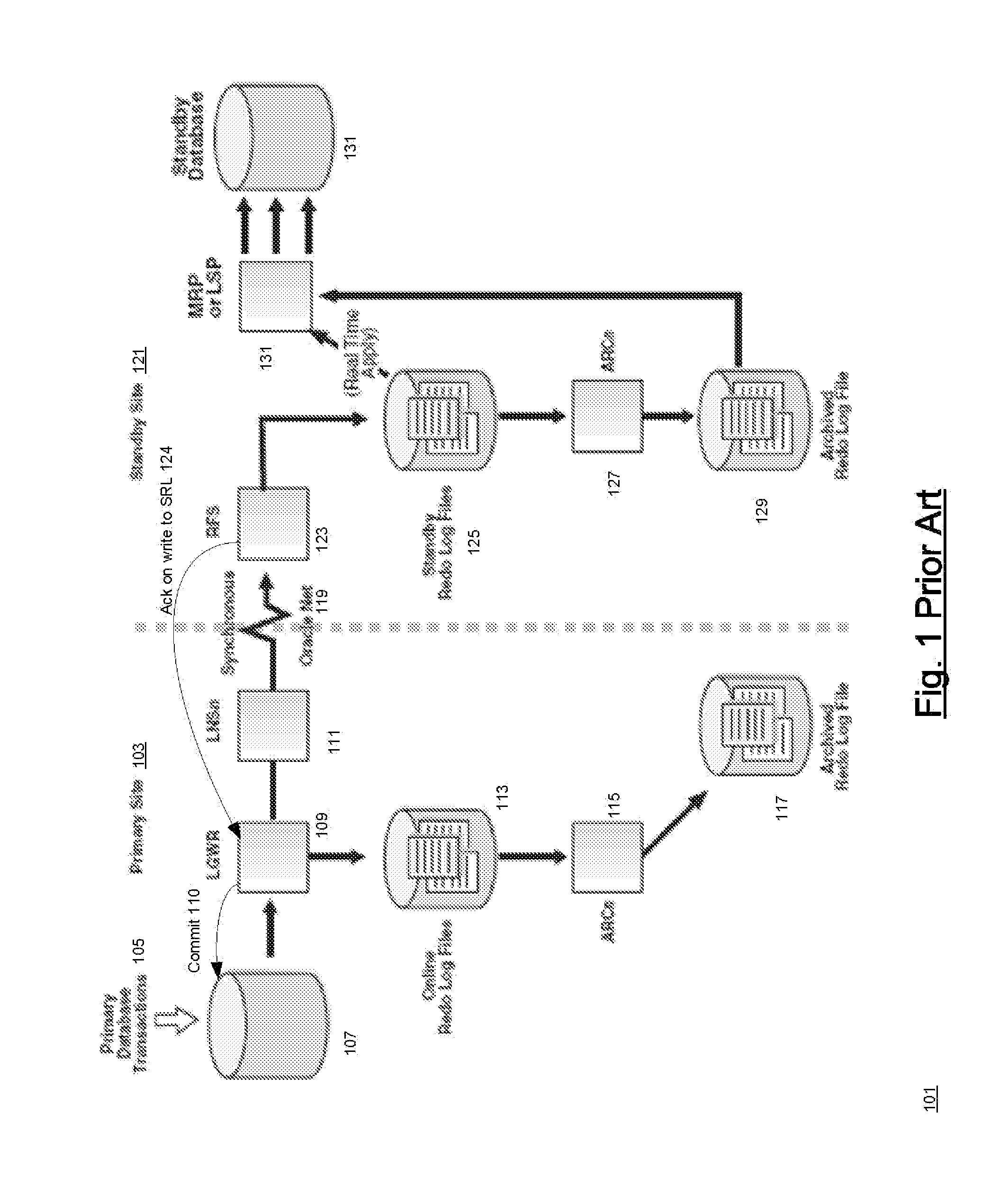
Consequently, simultaneous failure of the primary and the standby cannot result in loss of data for which a commit acknowledgment was sent to the user's session.
The disadvantage is the commit latency in the primary that results from the requirement that the standby wait until the redo data has been written to SRL 125 before sending commit signal 124 to the primary.
There are many circumstances in which the prior art's tradeoff between data protection and commit latency is not optimum.

Method used


Image

  • No data loss system with reduced commit latency
  • No data loss system with reduced commit latency
  • No data loss system with reduced commit latency

Examples


Embodiment Construction

Overview of the Invention: FIG. 5

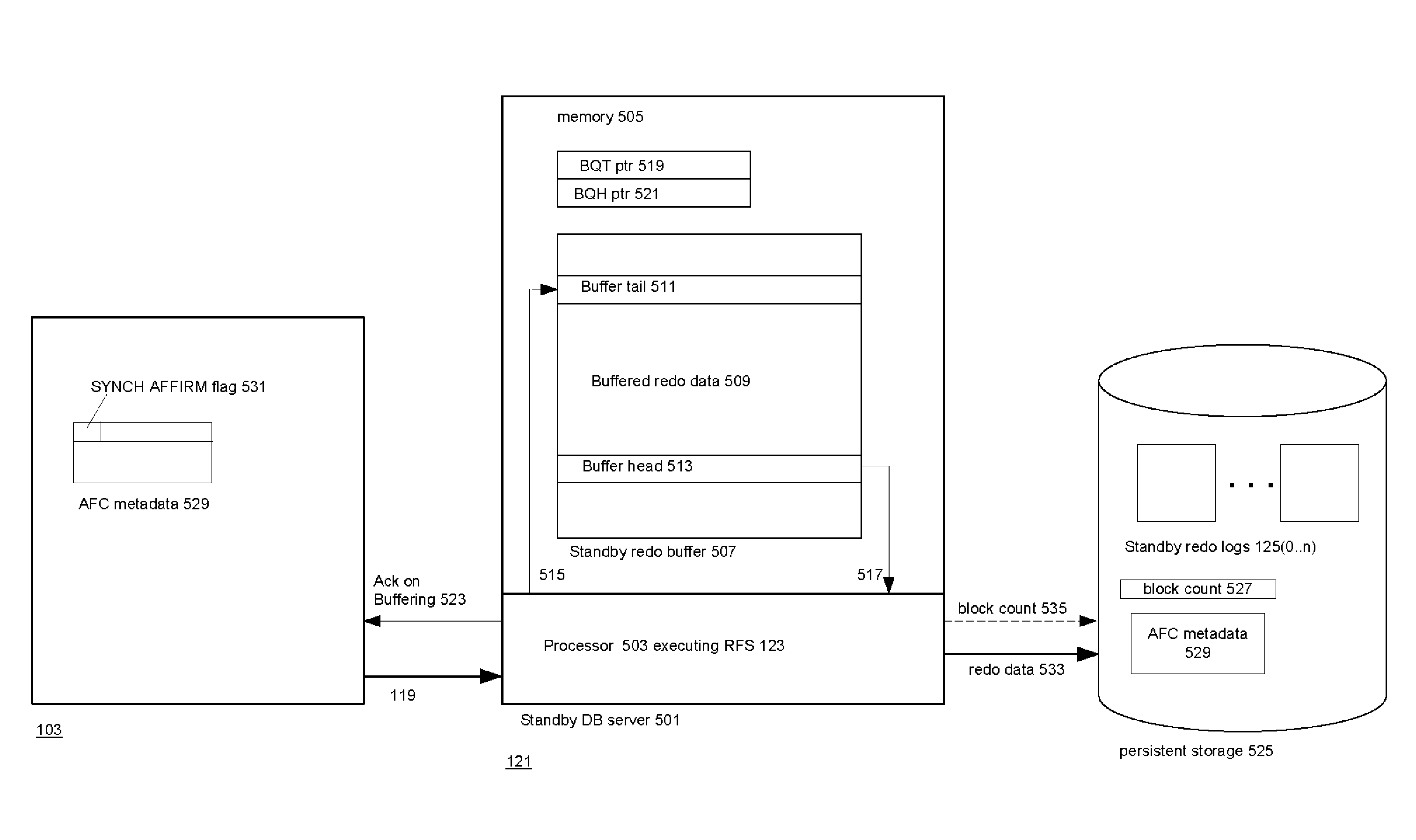
[0061]The invention reduces commit latencies at the primary database while maintaining the data loss guarantees of Maximum Availability as long as the primary and the standby do not become unavailable simultaneously. The invention thus takes advantage of the fact that simultaneous failures of the primary and the standby are extremely rare.

[0062]Since that is the case, double failures will generally be sequential: either the primary will fail before the standby or vice-versa. In the first case, the standby will be able to continue processing the redo data that it received from the primary prior to the primary's failure but has not yet written to SRL 125; in the second case, when the standby fails, the primary has its copy of the data up to the point where the standby failed.

[0063]Because simultaneous failure is the only situation where the primary fails and the standby will not be able to store all of the redo data it has received thus far from the pr...


PUM


Abstract

Techniques for reducing commit latency in a database system having a primary database system and a standby database system that is receiving a stream of redo data items from the primary. The standby sends an acknowledgment for a received item of redo data before the standby writes the redo data item to a redo log for the stream. When a no more redo event occurs in the standby, the standby sets a “no data lost flag” in the redo log if the stream of redo data items has no gaps and all of the redo data items received in the standby have been written to the redo log. The database system may operate in a first mode in which an acknowledgment is sent as just described and a second mode in which an acknowledgment is sent after the redo data item has been written to the redo log.

Description

CROSS-REFERENCE TO RELATED APPLICATIONS[0001]Not applicableSTATEMENT REGARDING FEDERALLY SPONSORED RESEARCH OR DEVELOPMENT[0002]Not applicable.REFERENCE TO A SEQUENCE LISTING[0003]Not applicable.BACKGROUND OF THE INVENTION[0004]1. Field of the Invention[0005]The invention is related generally to database systems and is more particularly related to database systems which include a primary database system and a standby database system. As the primary database executes transactions, it sends data to the standby database system which permits the standby database system to construct a replica of the current state of the database in the primary database system. If the primary database system fails, the standby can immediately take over for it.[0006]2. Description of Related ArtOverview of High-Availability, Low Data Loss Database Systems[0007]Users of database systems have always been concerned with losing data, and consequently, many techniques have been developed for archiving the infor...

Claims


Application Information

Patent Timeline
Patent Type & Authority Applications(United States)
IPC IPC(8): G06F17/30
CPCG06F11/2074G06F11/2076Y10S707/99953G06F17/30575G06F11/2082G06F16/27
Inventor GIRKAR, MAHESH BABURAOMCGEE, STEVENGAGNE, DAVID
Owner ORACLE INT CORP
Learn More