System and method for detecting status changes in a network using virtual coordinate mapping

a network status and network technology, applied in the field of system and method for detecting status changes in a network using virtual coordinate mapping, can solve the problems of difficult to quickly know the status of the network around remote nodes, the network routing information does not usually propagate, and the monitoring process is not scalable, so as to make the monitoring network more scalable

Inactive Publication Date: 2008-09-25
IBM CORP
View PDF0 Cites 13 Cited by
  • Summary
  • Abstract
  • Description
  • Claims
  • Application Information

AI Technical Summary

Benefits of technology

[0008]A system and method for scalable status change detection in a network of nodes includes embedding node coordinate positions into a virtual map environment. A cluster of nodes are represented with a representative node to form a hierarchy of nodes and clusters where changes in a status of the representative node imply a status change in the nodes of the cluster. By selectively monitoring the representative nodes for the changes in status, the representative nodes create a capability for scalable monitoring of the network.
[0010]Another system / method for scalable status change detection in a network of nodes includes embedding node coordinate positions into a virtual map environment, and representing a cluster of nodes with a representative virtual map to form a hierarchy of virtual maps representing clusters and subclusters of nodes such that changes in a status of the representative virtual map implies a status change in the nodes of the cluster or subcluster. The representative virtual maps are selectively monitored for the changes in status such that the representative virtual maps create a capability for scalable monitoring of the network.

Problems solved by technology

However, the routing change information of a remote network does not usually propagate to the other parts of the internet because of the BGP (border gateway protocol) policy routing.
So it is quite difficult to quickly know the network status around remote nodes.
However, if the number of nodes of interest is high, the monitoring process is not scalable.

Method used


Image

  • System and method for detecting status changes in a  network using virtual coordinate mapping
  • System and method for detecting status changes in a  network using virtual coordinate mapping
  • System and method for detecting status changes in a  network using virtual coordinate mapping

Examples


Embodiment Construction

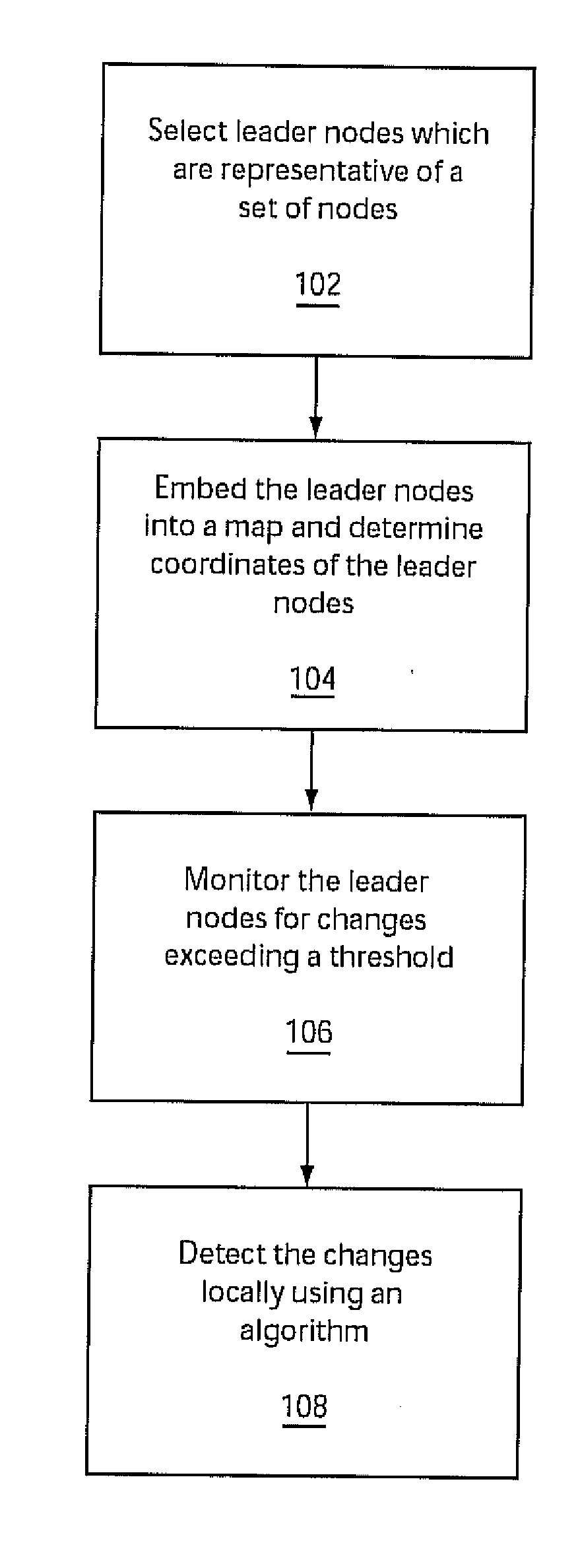
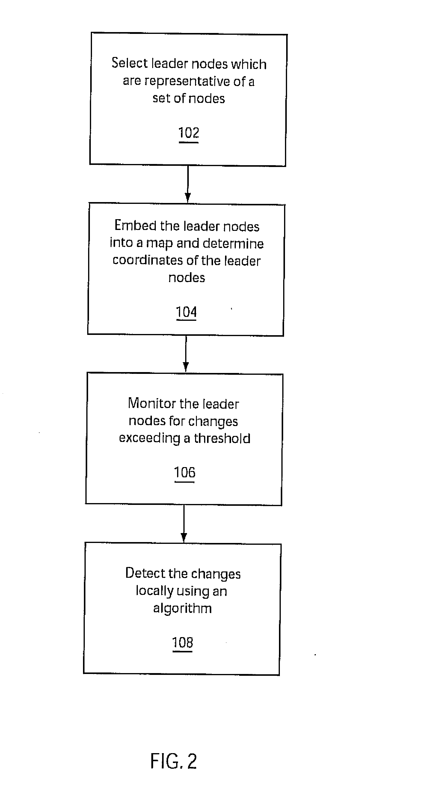
[0022]Exemplary embodiments of the present invention provide a scalable adaptive network monitoring system and method. Target nodes are grouped into a number of clusters. The nodes in a cluster are preferably in a close area. In other words, the network status change of a node implies the network status change of other nodes. However, it is quite difficult to find out which nodes are close to which.

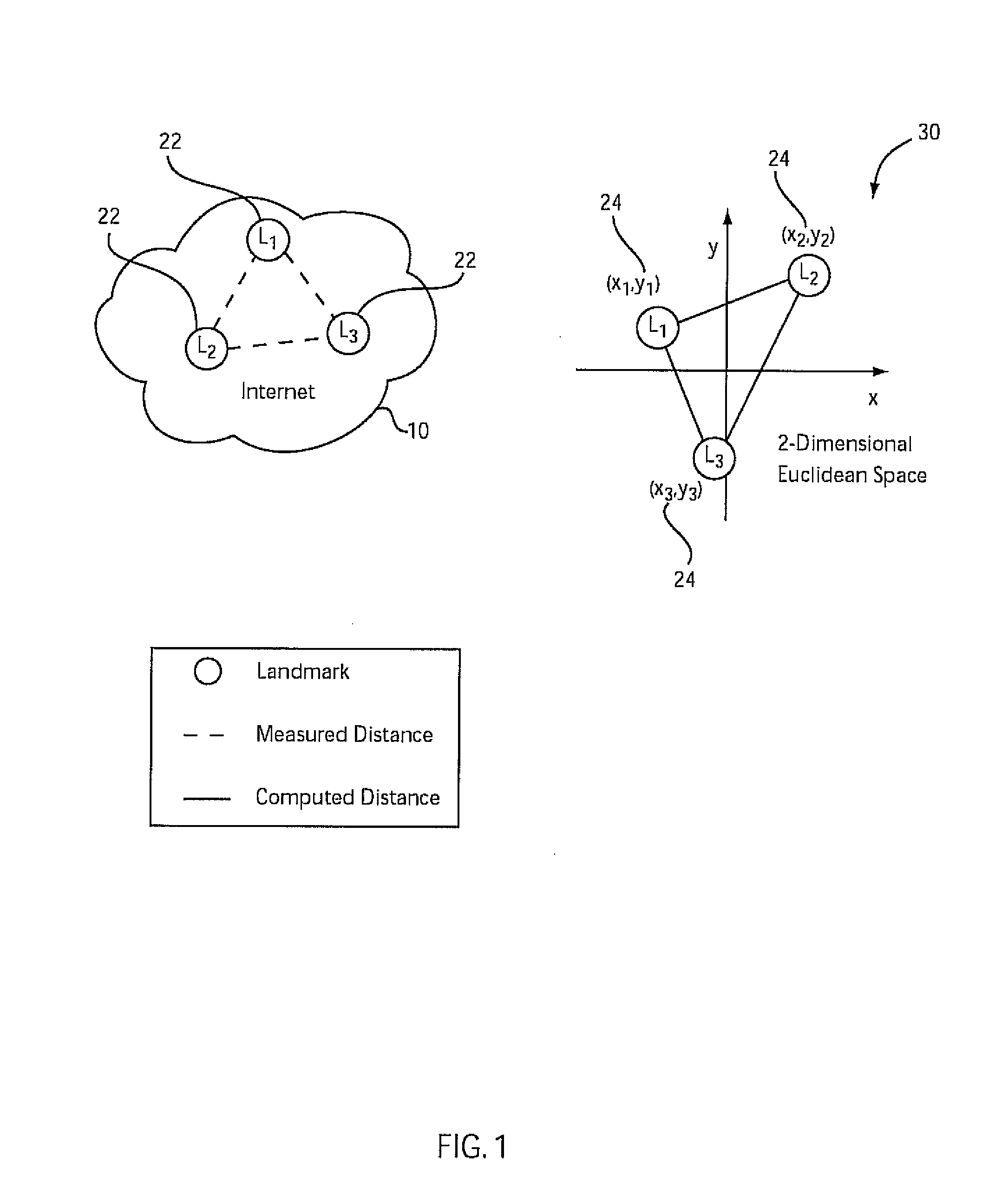
[0023]A virtual coordinate system is employed where a set of ping points, landmarks or other reference positions are chosen in the Internet or other network. Distances from the references to the target nodes are measured. Based on the network distances from the references to the target nodes, a set of virtual coordinates are computed in 2 or 3 dimensional Euclidean space for each target node in such a way that the network distance is estimated by a geometric distance in the Euclidean space. Since the virtual coordinate system provides a method to estimate the distance among hosts, cluster...


PUM


Abstract

A system and method for scalable status change detection in a network of nodes includes embedding node coordinate positions into a virtual map environment. A cluster of nodes are represented with a representative node to form a hierarchy of nodes and clusters where changes in a status of the representative node imply a status change in the nodes of the cluster. By selectively monitoring the representative nodes for the changes in status, the representative nodes create a capability for scalable monitoring of the network.

Description

RELATED APPLICATION INFORMATION[0001]This application is a Continuation application of co-pending U.S. patent application Ser. No. 11 / 214,102 filed Aug. 29, 2005, incorporated herein by reference in its entirety.BACKGROUND[0002]1. Technical Field[0003]The present invention relates to a scalable, hierarchical system and method for quickly detecting network anomalies or large changes in network delay using a scalable end-to-end approach.[0004]2. Description of the Related Art[0005]Users or network operators often intend to monitor the status of different parts of a network continuously to detect anomalies quickly. Current internet routing protocols link status monitoring and adjust the routing table to detour failed links. However, the routing change information of a remote network does not usually propagate to the other parts of the internet because of the BGP (border gateway protocol) policy routing. For some applications like overlay network or p2p (peer to peer) network, the numbe...

Claims


Application Information

Patent Timeline
Patent Type & Authority Applications(United States)
IPC IPC(8): G06F15/173
CPCH04L12/2602H04L43/00H04L43/0817H04L43/0829H04L67/1089H04L43/0864H04L67/104H04L67/1051H04L67/1059H04L43/0852
Inventor HALEY, MICHAEL R.LEE, SANGHWANPRADHAN, PRASHANTSAHA, DEBANJANSAHU, SAMBIT
Owner IBM CORP
Why Eureka
Try Eureka