Robot cleaner with improved dust collector

a robot cleaner and dust collector technology, applied in the field of robot cleaners, can solve the problems of limiting the suction force of heavy dust into the filter, the robot cleaner cannot adopt a large-size fan motor providing a high suction force, and the robot cleaner is difficult to exhibit a satisfactory cleaning performan

Active Publication Date: 2008-10-02
SAMSUNG ELECTRONICS CO LTD
View PDF4 Cites 89 Cited by
  • Summary
  • Abstract
  • Description
  • Claims
  • Application Information

AI Technical Summary

Benefits of technology

[0040]The at least one first collecting region and the second collecting region may each include at least one w...

Problems solved by technology

However, the robot cleaner has a problem of not being able to adopt a large-size fan motor providing a high suction force because it should be configured to have a small size and low height to clean under furniture, such as a sofa, and has only a restricted battery capacity.
As a result, the robot cleaner generally uses a fan motor having a significantly lower capacity (approximately 30˜100 W) than a capacity (approximately 600 W) of a conventional vacuum cleaner, and has a limit to suction heavy dust into the filter...

Method used


Image

  • Robot cleaner with improved dust collector
  • Robot cleaner with improved dust collector
  • Robot cleaner with improved dust collector

Examples


first embodiment

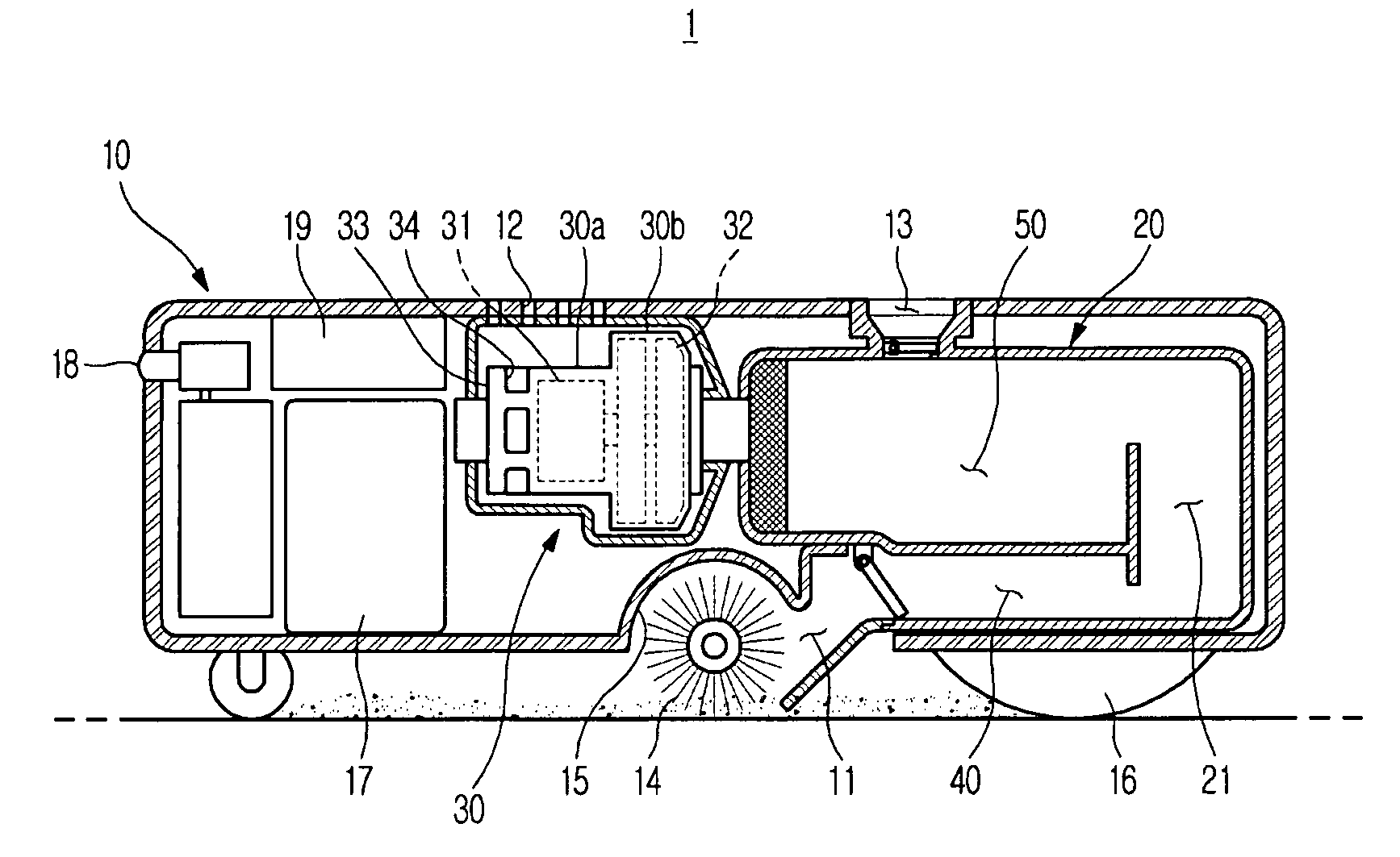
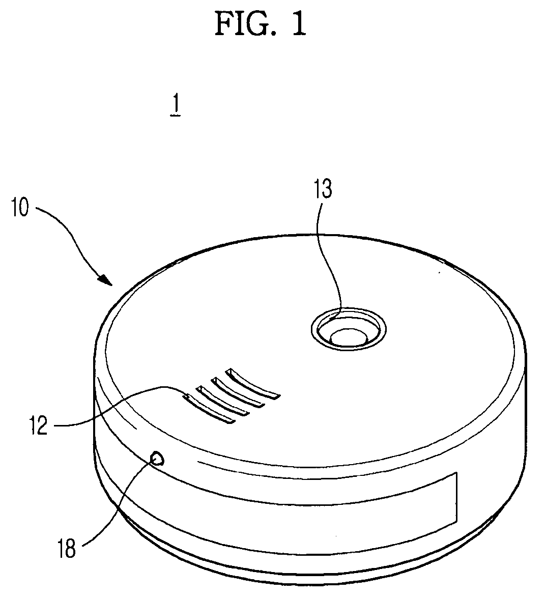
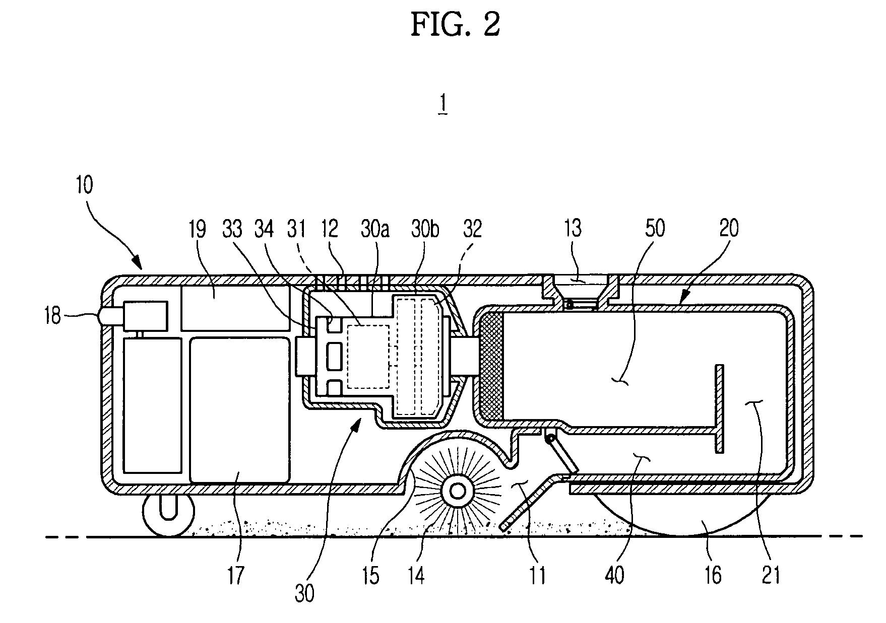
[0052]FIG. 1 is a perspective view of a robot cleaner according to the present embodiments, and FIG. 2 is a sectional view illustrating the overall configuration of a robot cleaner according to a

[0053]The robot cleaner according to the first embodiment, as shown in FIGS. 1 and 2, includes a body 10 defining an outer appearance of the cleaner 1, a dust collector 20 installed in the body 10 to collect dust, scraps, etc. (hereinafter, wholly referred to as “dust”) therein, and a blower 30 to generate a suction force required to suction the dust in communication with the dust collector 20.

[0054]The body 10 defining the outer appearance is perforated, in a bottom surface thereof, with a suction hole 11 to suction dust from the floor. Also, the body 10 is perforated, in a top surface thereof, with air-discharge slots 12 to discharge air suctioned by the blower 30 to the outside of the body 10 and a dust-discharge hole 13 to discharge the dust collected in the dust collector 20 into a dock...

second embodiment

[0094]Next, a robot cleaner will be described.

[0095]In the following description, the same configurations as those of the robot cleaner according to the previously described first embodiment will be designated by the same reference numerals and a description thereof will be omitted.

[0096]The robot cleaner according to the second embodiment is approximately the same as the robot cleaner according to the first embodiment except for the configuration of a dust collector.

[0097]FIG. 6 is a sectional view illustrating the overall configuration of the robot cleaner according to the second embodiment. FIG. 7 is a perspective view illustrating a dust collector included in the robot cleaner according to the second embodiment. Also, FIG. 8 is a sectional view taken along the line A-A of FIG. 7, and FIG. 9 is a sectional view taken along the line B-B of FIG. 7.

[0098]The dust collector 60 included in the robot cleaner according to the second embodiment, as shown in FIG. 6, has an approximately ...


PUM


Abstract

A robot cleaner having a configuration capable of improving an ability to collect dust, etc. is disclosed. The robot cleaner includes a suction hole to suction dust, a dust collector to receive the dust suctioned through the suction hole, and a rotating brush provided at a side of the suction hole. The robot cleaner is configured to sweep up and collect the dust into the dust collector by a drive force of the rotating brush.

Description

CROSS-REFERENCE TO RELATED APPLICATIONS[0001]This application claims the benefit of Korean Patent Application No. 2007-0030059, filed on Mar. 27, 2007 in the Korean Intellectual Property Office and Korean Patent Application No. 2007-0099735, filed on Oct. 4, 2007 in the Korean Intellectual Property Office, the disclosure of which is incorporated herein by reference.BACKGROUND[0002]1. Field[0003]The present invention relates to a robot cleaner, and, more particularly, to a robot cleaner configured to achieve an improved cleaning performance.[0004]2. Description of the Related Art[0005]A cleaner is an appliance to eliminate dirt and clean a room. Generally used is a vacuum cleaner to suction dirt by use of a suction force generated from a low-pressure unit.[0006]Recently, the development of a robot cleaner is underway. The robot cleaner eliminates dirt from the floor by a self-running function thereof without a user's labor.[0007]One example of the robot cleaner is disclosed in Korean...

Claims


Application Information

Patent Timeline
IPC IPC(8): A47L9/04A47L9/28A47L9/00A47L5/00
CPCA47L7/02A47L11/33A47L11/4013A47L9/14A47L11/4044A47L2201/00A47L11/4041
Inventor KIM, DONG WONWEE, HOONHONG, JUN PYOKIM, YONG TAECHUNG, WOO RAM
Owner SAMSUNG ELECTRONICS CO LTD
Why Eureka
Try Eureka