
Beverage Dispenser and Sealed Dispensing unit

a technology of beverage dispenser and dispensing unit, which is applied in the direction of pliable tubular containers, domestic cooling devices, lighting and heating devices, etc., and can solve problems such as the uselessness of supplying coolers

Inactive Publication Date: 2008-10-02
WOLEK PAUL LEON
View PDF3 Cites 18 Cited by
  • Summary
  • Abstract
  • Description
  • Claims
  • Application Information

AI Technical Summary

Benefits of technology

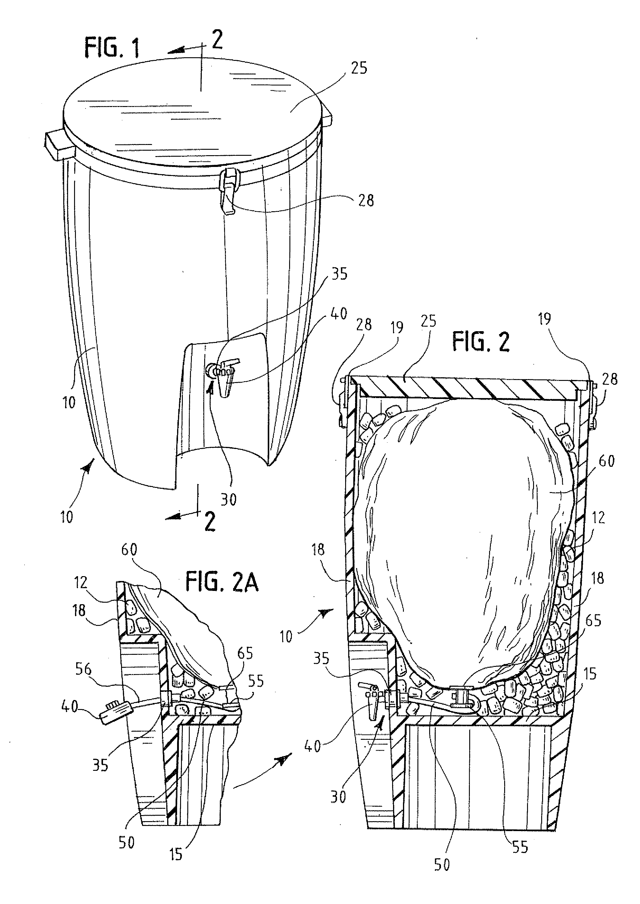
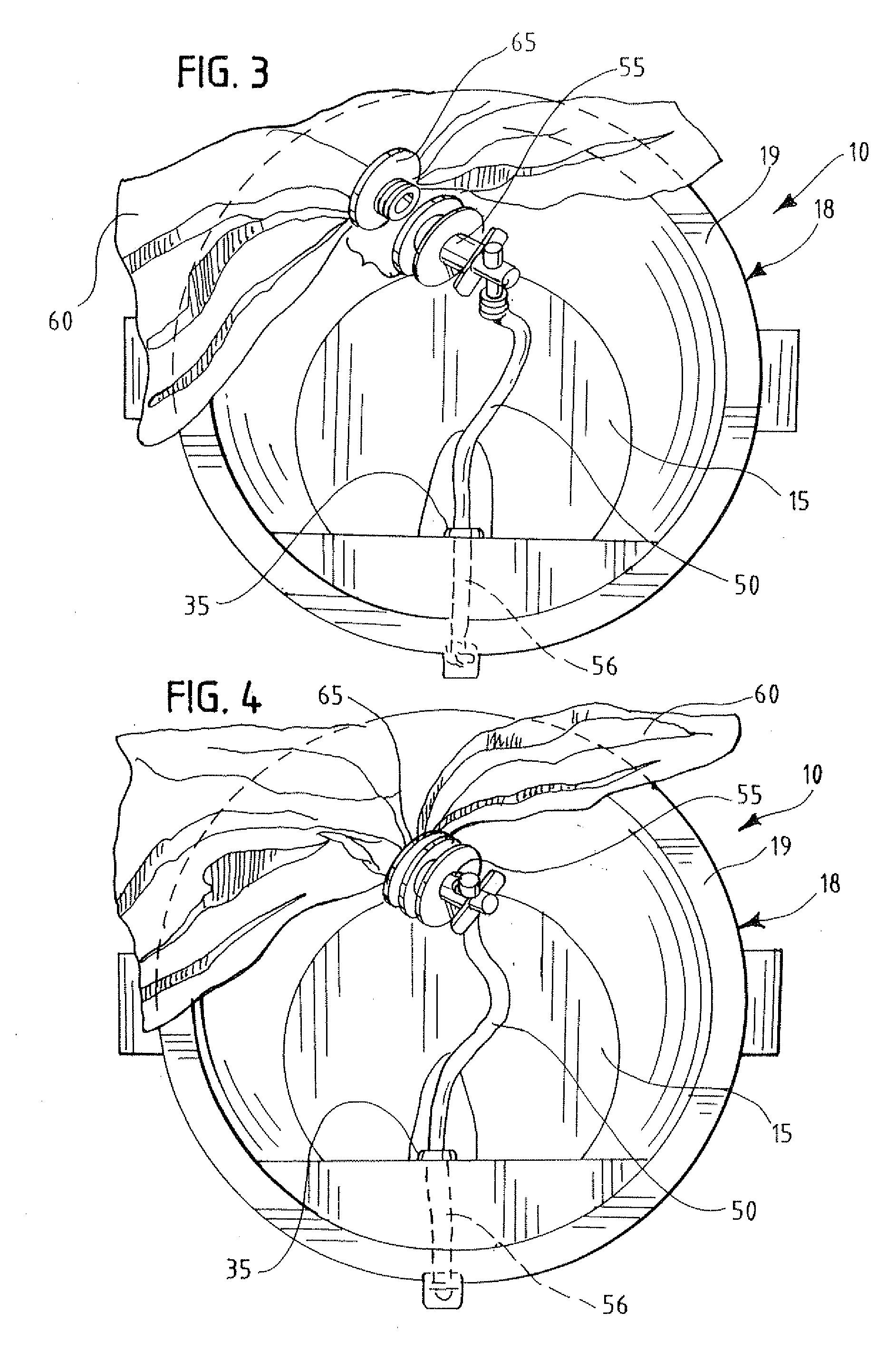
[0005]The invention described herein is a beverage cooler, equipped with an external spigot in fluid communication with an internal bag or bladder, the bladder containing the beverage to be dispensed. The bag is typically connected to the external spigot by a length of hose or other conduit. The bag or bladder includes a fitting, and the hose includes a complimentary fitting that allows the bag to be attached to the conduit for dispensing of the beverage, and subsequent removal from the conduit or hose when the bladder is empty. Once the bag is connected, ice can be placed in the cooler to keep the beverage cold. Such a system eliminates waste, as ice can continually be added to the cooler to keep the beverage cold and preserved. Since the bag or bladder does not include a vent and remains sealed, air does not enter the bladder and thus preventing contaminating or providing oxygen to the contents therein.
[0007]A further improvement on the system, is to provide a spigot that is flexible, as it is often complained of, especially in the utility truck market, that the spigot is exposed and gets broken off of the side of the cooler, thus rendering the cooler useless. Such a flexible spigot can include a length of flexible hose connected to the external wall of the cooler and being in fluid communication with the hose that leads to the bladder, the external hose could then be connected to a valve, spigot, or other device to selectively control the flow of fluid. Since the hose is flexible, knocking or other movement of the valve should not dislodge or damage the valve, but rather the hose should flex to allow the valve to remain undamaged.

Problems solved by technology

A further improvement on the system, is to provide a spigot that is flexible, as it is often complained of, especially in the utility truck market, that the spigot is exposed and gets broken off of the side of the cooler, thus rendering the cooler useless.

Method used


Image

  • Beverage Dispenser and Sealed Dispensing unit
  • Beverage Dispenser and Sealed Dispensing unit
  • Beverage Dispenser and Sealed Dispensing unit

Examples


Embodiment Construction

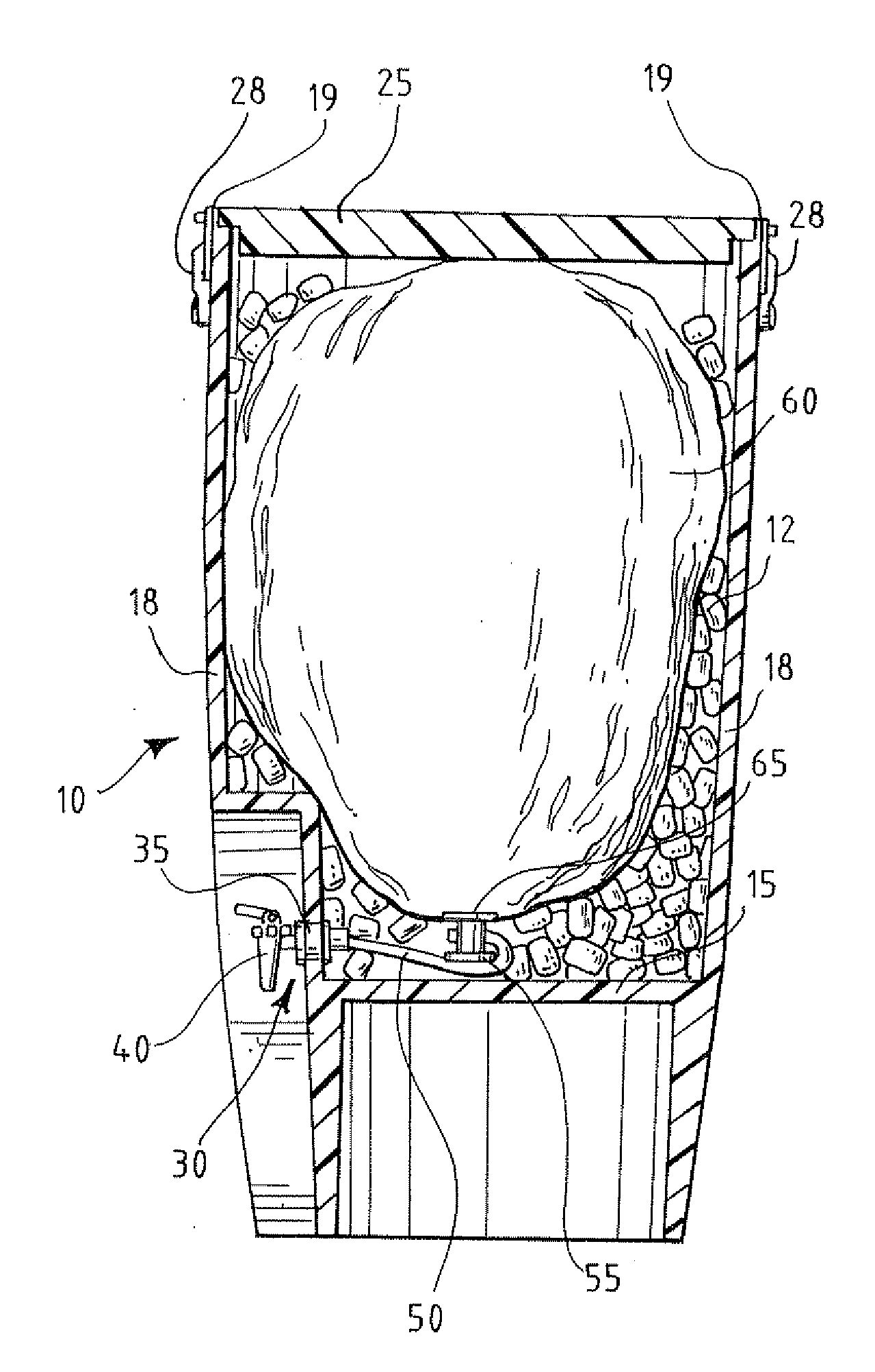
[0014]As shown in the figures, with particular reference to FIGS. 1 and 2, the cooler 10 disclosed herein includes a base 15 which is generally circular, and a wall 18 or walls extending upwardly therefrom to form a bucket or container. In the preferred embodiment, the walls 18 are cylindrical, but one skilled in the art will recognize that the walls can take any shape, so long as they form a container capable of holding ice 12. It is preferable that the walls 18 and base 15 are insulated, so that the contents inside can be maintained at a desired temperature, independent of the external environmental variables. The cooler 10 also contains a lid 25, which can be attached to the ends 19 of the walls 18 to form a closed container. As with the walls 18 and base 15, the lid 25 may also be insulated. The lid 25 can include a latch 28 or a plurality of latches to secure the lid 25 in place on top of the walls 18. Optionally, the cooler 10 may also include handles to allow easy transport.

[...


PUM


Abstract

The invention described herein is a beverage cooler, equipped with an external valve or spigot in fluid communication with an internal bag or bladder, the bladder containing the beverage to be dispensed. The bag is typically connected to the external spigot by a length of hose or other conduit. The bag or bladder includes a fitting, and the hose includes a complimentary fitting that allows the bag to be attached to the conduit for dispensing of the beverage, and subsequent removal from the conduit or hose when the bladder is empty. Once the bag is connected, ice can be placed in the cooler to keep the beverage cold.

Description

RELATED APPLICATIONS[0001]This application claims priority to provisional application 60 / 828,149 filed on Oct. 4, 2006, the contents of which is incorporated by reference in its entirety.FIELD OF INVENTION[0002]This invention is related to beverage dispensers and coolers.BACKGROUND[0003]The use of coolers and other beverage dispensers to provide cool refreshing beverages to thirsty individuals are well known in the art. Perhaps most well known or most publicized are the Gatorade® coolers used by celebratory professional and amateur athletes to douse the winning coach in a shower of ice cold, sugary isotonic sports drink. Such coolers are also deployed within factories to provide hydration for workers. Such coolers are also deployed in the field on utility trucks and can also be found at various points on golf courses.[0004]While the beverage cooler is well known, it is not without its problems. Typically, the lids on such coolers, are not secured in any fashion. Thus, it is easy for...

Claims


Application Information

Patent Timeline
IPC IPC(8): B65D35/56F25D3/08B67D5/62B67D5/06B67D7/06B67D7/80
CPCB67D3/0009B67D3/0054B67D3/0067F25D3/08F25D31/006F25D2303/081F25D2303/0843F25D2303/0844F25D2303/0845F25D2331/806
Inventor WOLEK, PAUL LEON
Owner WOLEK PAUL LEON
Learn More