Piezoelectric motor and piezoelectric motor system
a piezoelectric motor and piezoelectric technology, applied in piezoelectric/electrostrictive/magnetostrictive devices, piezoelectric/electrostriction/magnetostriction machines, electrical apparatus, etc., can solve the problems of increasing the size of the motor, reducing the range of movement, and the basic structure of the gimbal mechanism and the joint mechanism is not always satisfactory, so as to reduce the idle torque, improve the range of movement, and minimize device
- Summary
- Abstract
- Description
- Claims
- Application Information
AI Technical Summary
Benefits of technology
Problems solved by technology
Method used
Image
Examples
first modification
(FIRST MODIFICATION)
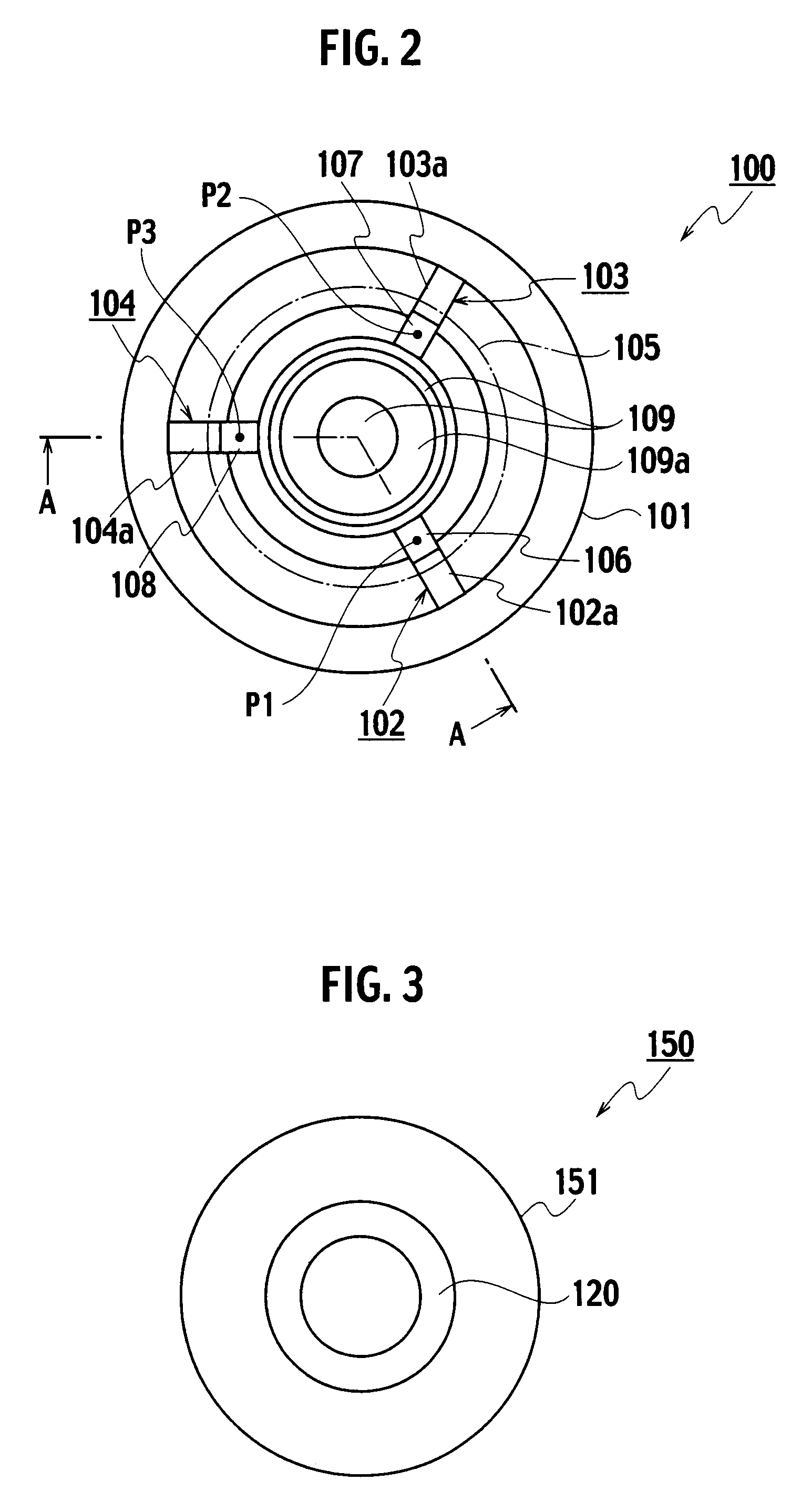
[0042]A description will be given of the structure of a variable-sight-line camera module including the piezoelectric motor 100 as a mount for such a camera module, as a first modification of the present invention. Referring to FIGS. 3 and 4, a variable-sight-line camera module 150 includes the piezoelectric motor 100, a driven target 151, and a camera module 120 embedded in the vicinity of a central potion on the inner side of the driven target 151.
[0043]The camera module 120 is fixedly disposed inside the driven target 151. The driven target 151 has a circumferential surface that provides a spherical shape, to which a driving force from the first to third piezoelectric units 102 to 104 is transmitted. Note that the variable-sight-line camera module 150 includes image processing means for performing rotation of a shot image, if necessary.
[0044]When the driven target 151 is rotationally driven by activating the piezoelectric motor 100, the direction of the sight ...
second modification
(SECOND MODIFICATION)
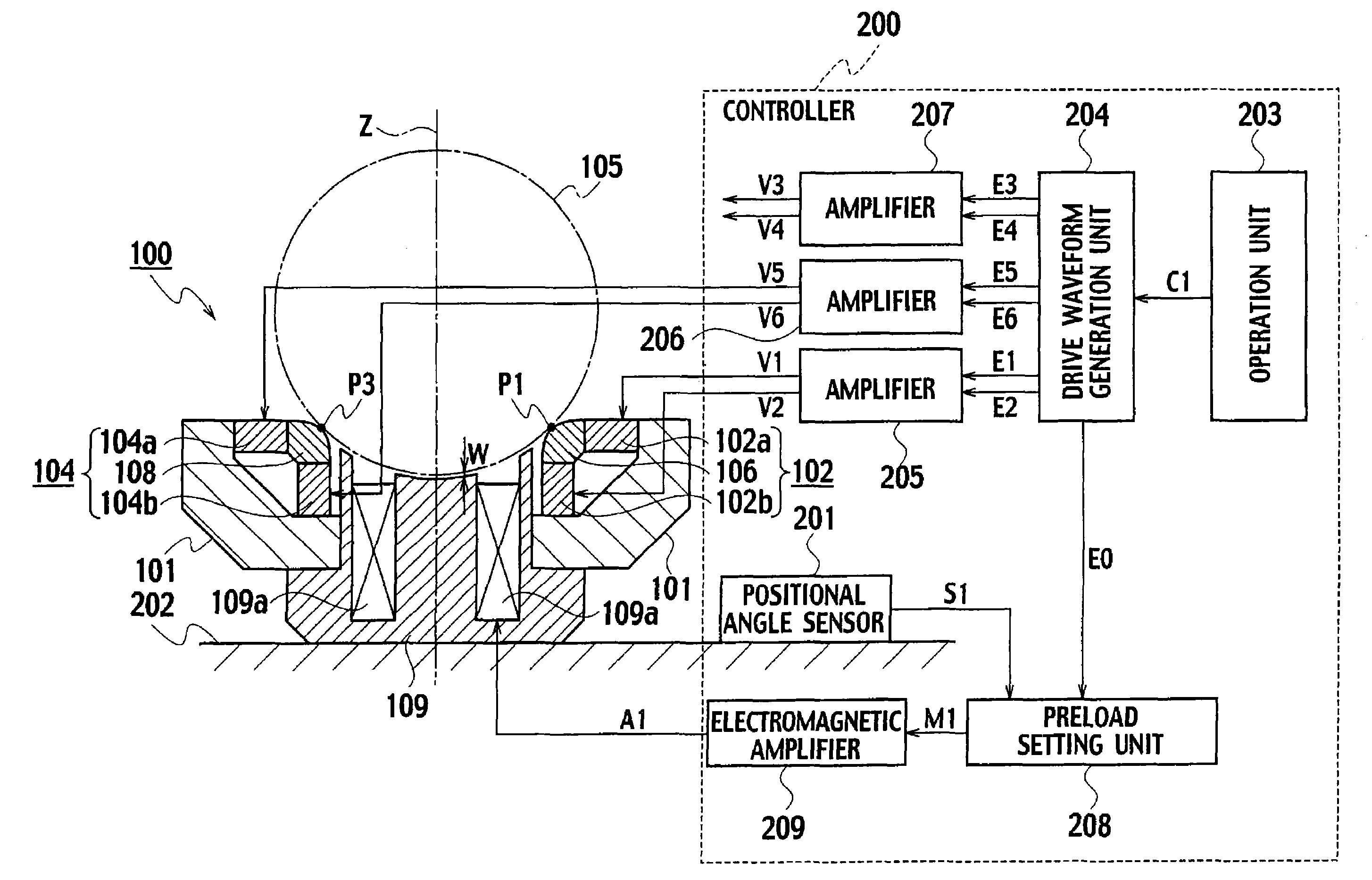
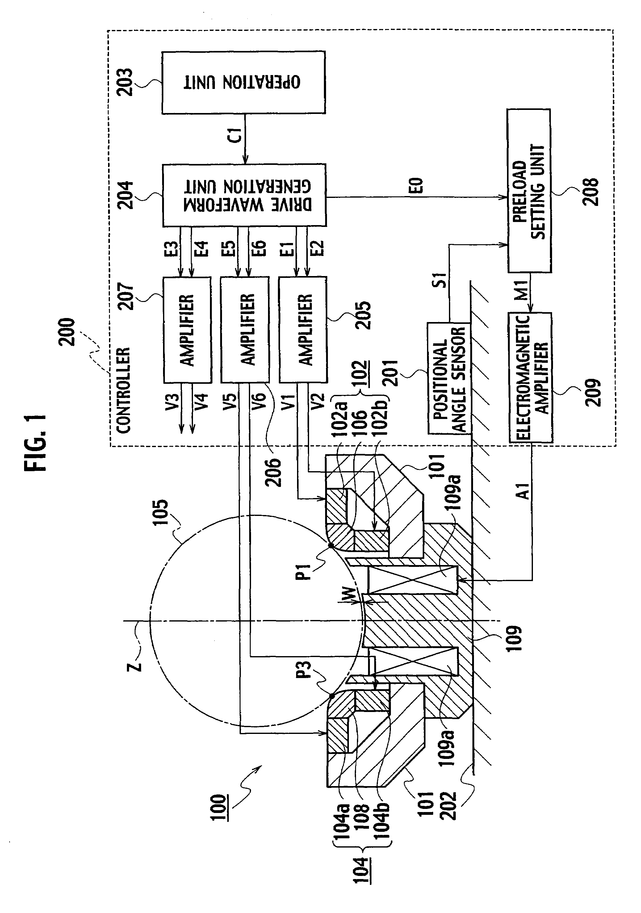
[0047]Referring to FIGS. 7 and 8, a piezoelectric motor 300 according to a second modification of the embodiment of the present invention includes: a driven target 105; a base 301 in a substantially annular shape; first to third piezoelectric units (three-degree-of-freedom piezoelectric units) 302 to 304 that are placed on the base 301 and are equidistantly disposed in the circumferential direction with a Z′ axis at the center, at an angle of 120 degrees with respect to each other; and an annular magnet 109 disposed so as to have a predetermined clearance w from the driven target 105 along the Z′ axis.
[0048]The annular magnet 109 applies a preload force to the first to third piezoelectric units 302 to 304 by magnetically attracting the driven target 105 without direct physical contact therewith.
[0049]In the first piezoelectric unit 302, first to third piezoelectric elements 302a to 302c are disposed so that their neutral axes intersect with each other at substan...
PUM
 Abstract
Description
Claims
Application Information
 - R&D Engineer
- R&D Manager
- IP Professional
- Industry Leading Data Capabilities
- Powerful AI technology
- Patent DNA Extraction
Browse by: Latest US Patents, China's latest patents, Technical Efficacy Thesaurus, Application Domain, Technology Topic, Popular Technical Reports.
© 2024 PatSnap. All rights reserved.Legal|Privacy policy|Modern Slavery Act Transparency Statement|Sitemap|About US| Contact US: help@patsnap.com


