Integrated distance measuring equipment and transponder system and method

a technology of integrated distance measuring equipment and transponder system, which is applied in the direction of instruments, measurement devices, and using reradiation, can solve the problems of large total system weight, high cost, and large coaxial cabling requirements, and achieve the effect of cost advantag

Active Publication Date: 2008-10-02
HONEYWELL INT INC
View PDF5 Cites 63 Cited by
  • Summary
  • Abstract
  • Description
  • Claims
  • Application Information

AI Technical Summary

Benefits of technology

The invention merges the functions of transponder and DME systems used on airplanes by creating a single device with multiple capabilities. This eliminates the need for separate components like L Band transmitters, reducing costs and allowing for more efficient usage of available space. Additionally, this combination enables the use of a single antenna for both functions, minimizing signal loss while still achieving optimal performance. Overall, this innovation offers improved functionality at lower expense.

Problems solved by technology

The technical problem addressed by this patent is reducing the amount of heavy and expensive equipment needed for current aviation safety standards that involve both transporters and distance measuring devices. Specifically, it seeks to decrease the number of antennas and transmitters necessary while also minimizing the overall weight and cost of these systems.

Method used


Image

  • Integrated distance measuring equipment and transponder system and method
  • Integrated distance measuring equipment and transponder system and method
  • Integrated distance measuring equipment and transponder system and method

Examples


Embodiment Construction

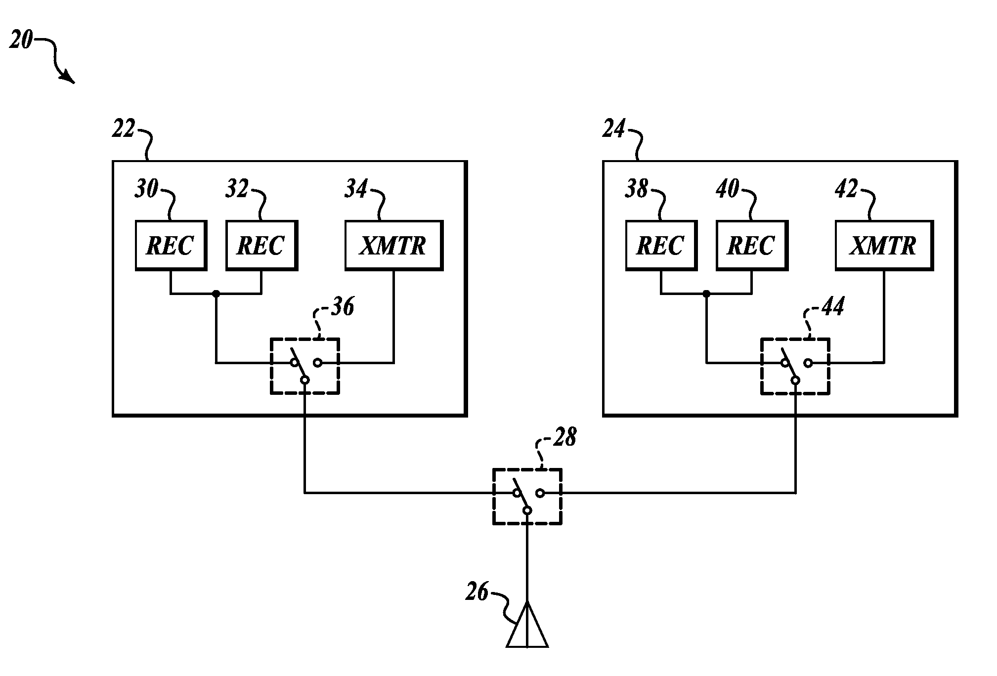
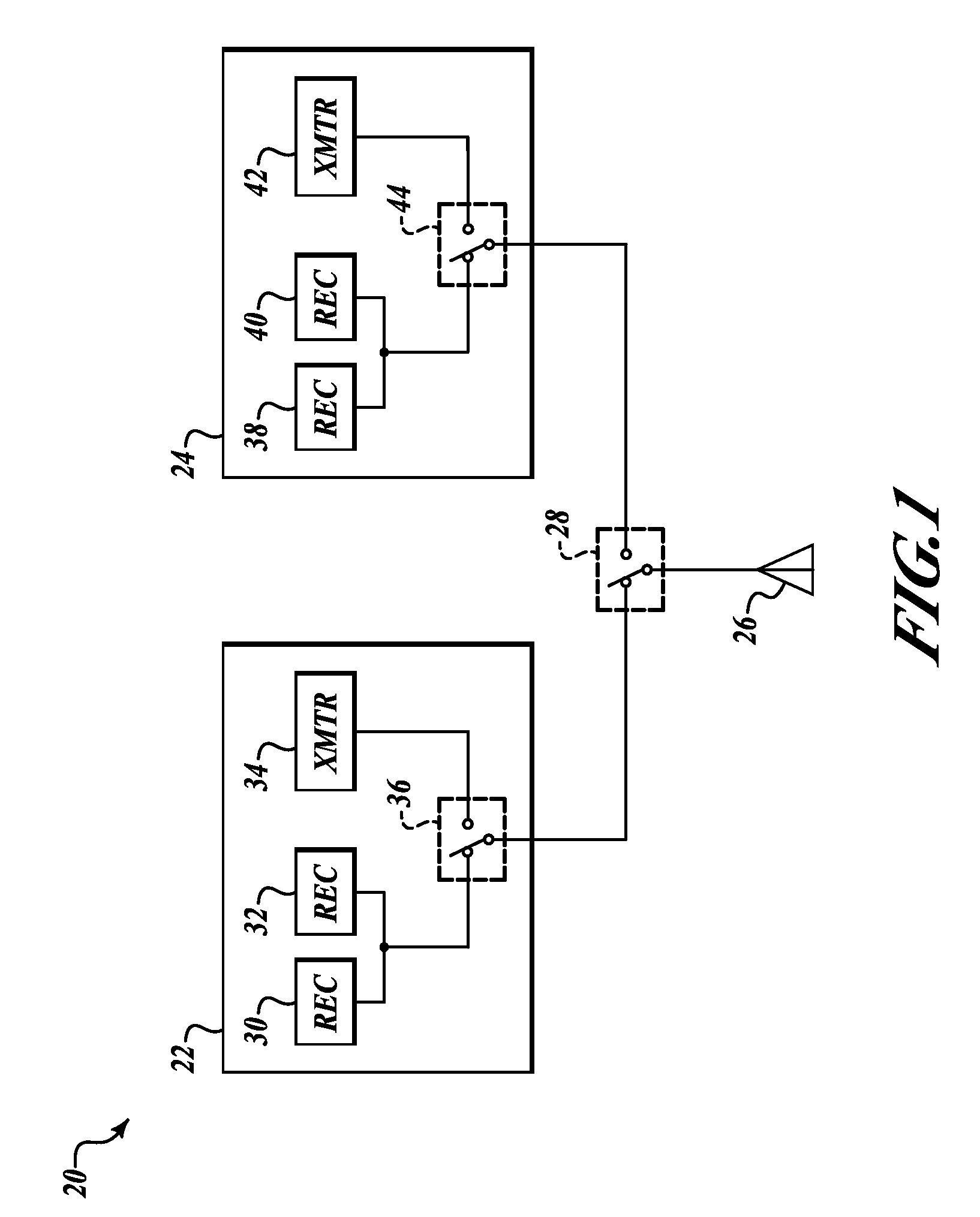
[0011]FIG. 1 is a block diagram of a combined transponder (XPDR) and distance measuring equipment (DME) system 20 for use in an aircraft formed in accordance with an embodiment of the invention. In an example embodiment, the system 20 is a redundant system that includes a first line replaceable unit (LRU) 22 and a second LRU 24 that are connected to an antenna 26 through an LRU1 / LRU2 switch 28. In an example embodiment, the antenna 26 is an L-band blade antenna. Each LRU 22 and 24 includes an integrated DME and XPDR transceiver system. The first LRU 22 includes a receiving path having a first receiver 30 and a second receiver 32. The first LRU 22 also includes a transmitter 34 linked to a TX / RX switch 36 that selectively connects either the transmitter 34 or the receivers 30 and 32 to a first lead of the LRU1 / LRU2 switch 28.

[0012]In similar fashion, the second LRU 24 includes a receiving path having a first receiver 38 and a second receiver 40. The second LRU 24 also includes a tran...


PUM


Abstract

A combined transponder and DME system for use in an aircraft. An L Band transmitter is shared between transponder and DME.

Description


Claims


Application Information

Patent Timeline
Owner HONEYWELL INT INC
Why Eureka
Try Eureka