Hold type image display system

a display system and image technology, applied in the direction of instruments, static indicating devices, etc., can solve the problems of circuit scale increase, difficult application of black insertion drives suitable for all methods, unclear moving image, etc., to improve the blur of moving image, enhance the image quality of moving image, and reduce luminance

Active Publication Date: 2008-10-02
NEC LCD TECH CORP
View PDF9 Cites 36 Cited by
  • Summary
  • Abstract
  • Description
  • Claims
  • Application Information

AI Technical Summary

Benefits of technology

[0013]It is an exemplary object of the invention to provide a hold type image display capable of inserting a black image in one frame period to reduce the moving image blur due to overlapping recognition of the current frame image and the afterimage of the frame one before and enhance the image quality of the moving image, and capable of setting the black insertion rate with respect to one frame period variably according to each usage state.
[0018]As an exemplary advantage according to the invention, the present invention can finely adjust the black insertion rate with respect to one frame period while taking into consideration the balance between the merit of improving the moving image blur and the demerit of lowering in luminance in the hold type display device, thereby enhancing the image quality of the moving image.

Problems solved by technology

However, in the hold type display device such as LCD, an image continues through a frame period as opposed to an impulse type display device such as CRT display, and thus a moving image tends to become unclear.
However, the liquid crystal display device of patent document 1 switches between a black display and a video display for every ½ frame period of an input signal, and thus the black insertion rate with respect to one frame is limited to ½. Thus, in the device of patent document 1, setting an optimum black insertion rate corresponding to each usage state with considering the balance between improvement in moving image blur, which is a merit of black insertion, and lowering in luminance, which is a demerit of black insertion, cannot be realized.
With the device of patent document 1, the application of the black insertion drive suited for all the methods was difficult.
Furthermore, in the liquid crystal display device of patent document 1, the circuit scale increases and also the cost increases since the drive frequency of the device is required to be doubled and a frame memory for temporarily storing video information becomes necessary.
However, when commercializing a product having a resolution used for TV, if the gate driver offered in the market is used, two gate drivers are generally used in the VA (Video Graphics Array), and three gate drivers are used in the XGA (Extended Graphics Array) and WXGA (Wide XGA), whereas, in the configuration of the device of patent document 1, the gate driver is limited to an even number, and thus the degrees of flexibility in selecting the number of gate drivers lower when it is applied to a product, and in some cases, an extra gate driver IC becomes necessary thereby a wasteful cost is required.
In the device of patent document 2, one gate driver starts the scanning of the video display, and at the same time, another gate driver specified in advance starts the scanning of the black display, and thus the black insertion rate can only be set at the segment of the gate driver and operation is performed with the fixed black insertion rate with respect to one frame, whereby it is difficult to set an optimum black insertion rate variably according to each usage state.
Furthermore, in the device disclosed in patent document 1, the continuous holding in a blanking period is not taken into consideration in the case of writing the black image over a plurality of frames.

Method used


Image

  • Hold type image display system
  • Hold type image display system
  • Hold type image display system

Examples


first exemplary embodiment

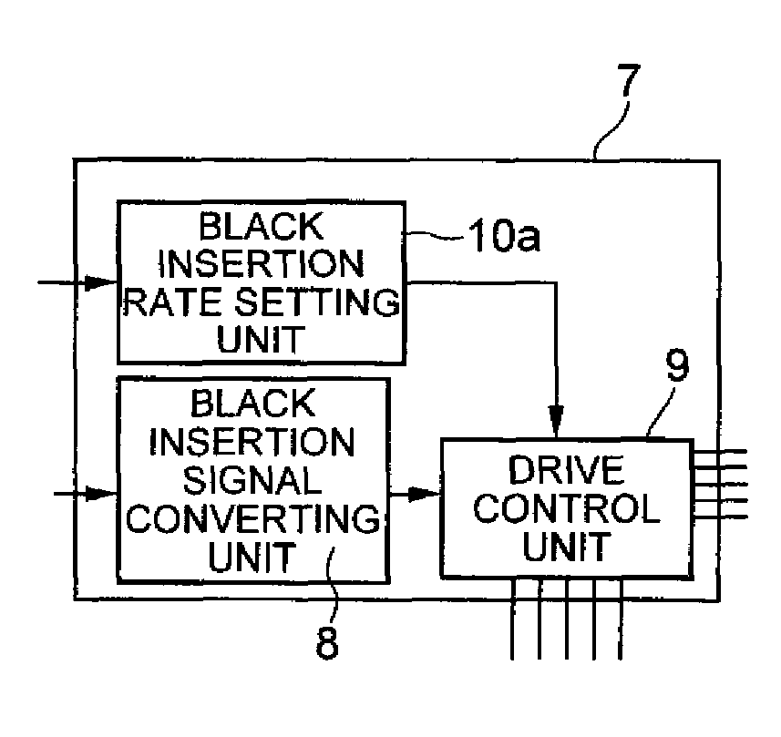
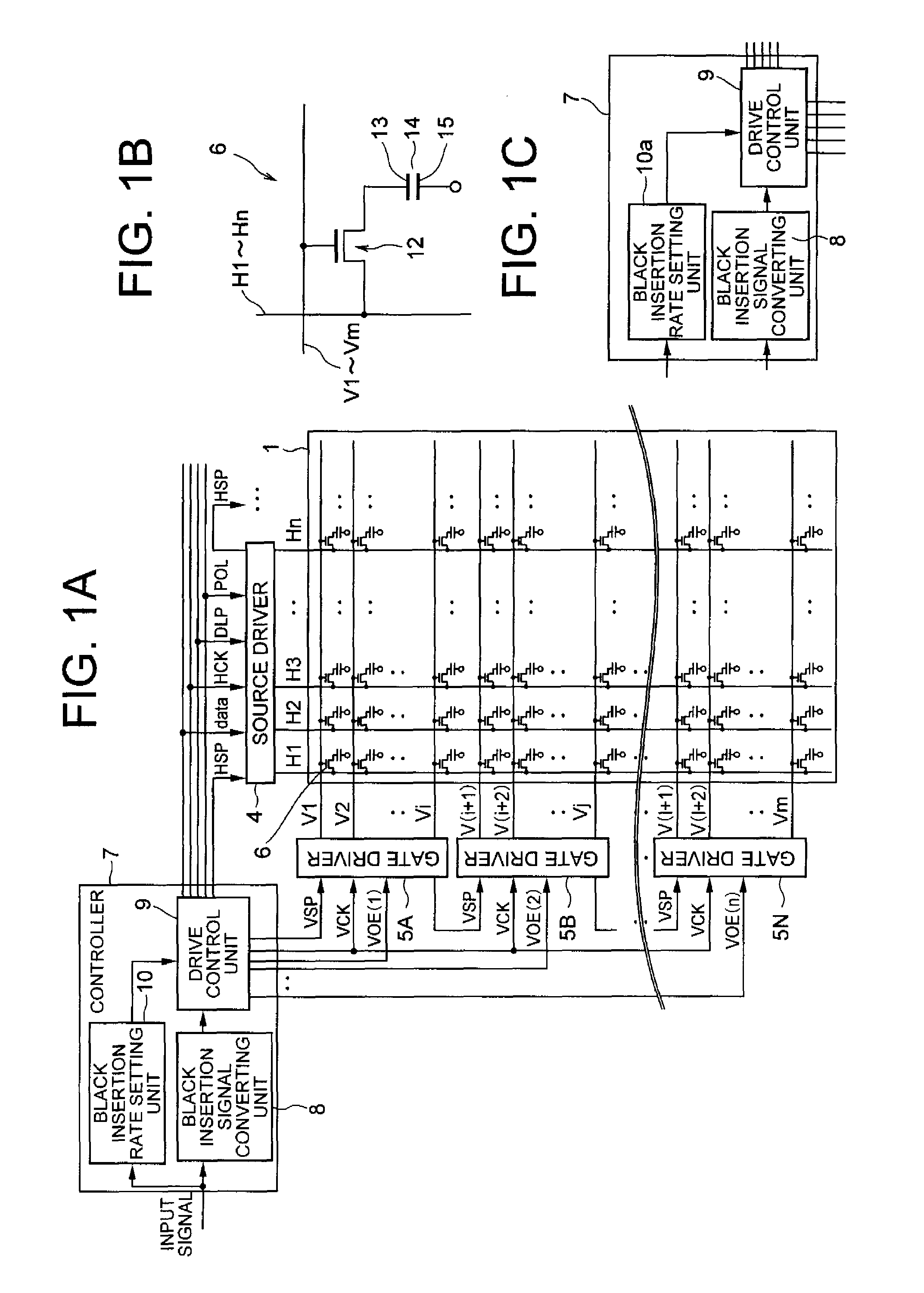
[0043]FIG. 1A is a view showing a configuration of an image display device of a first exemplary embodiment according to the present invention. As shown in FIG. 1A, the image display device of the first exemplary embodiment includes a display panel 1 in which m (m is a natural number) gate lines V1 to Vm and n (n is a natural number) source lines H1 to Hn are arranged so as to intersect each other to a grid form, a pixel 6 being formed at each intersection of the gate lines V1 to Vm and the source lines H1 to Hn; a source driver 4, connected to each source line H1 to Hn, for providing a video signal; and a plurality of gate drivers 5A to 5n, arranged with respect to each gate line group, where the plurality of gate lines V1 to Vm are divided into a number of groups, for sequentially providing a gate-ON signal (Vg) to the corresponding gate lines V1 to Vm.

[0044]As shown in FIG. 1A, i number of gate lines V1 to Vi from the top are connected to the gate driver 5A, i+1th to jth gate line...

second exemplary embodiment

[0084]A second exemplary embodiment of the present invention will now be described.

[0085]FIG. 8 is a view showing a configuration of an image display device of a second exemplary embodiment according to the present invention. Same reference numerals are denoted for components same as in the first exemplary embodiment shown in FIG. 1A. As shown in FIG. 8, the second exemplary embodiment has a backlight 21 arranged at the rear surface of the display panel 1 when seen from the user, in addition to the configuration similar to the first exemplary embodiment. A black insertion rate setting unit 20 has a function of temporarily storing information for one frame of the input video signal sequentially input for every frame, comparing the video signal of one frame of the input video signal and the video signal of the previous frame that is temporarily stored, and determining the black image insertion rate and the light control luminance of the backlight based on the changed number of data, a...


PUM


Abstract

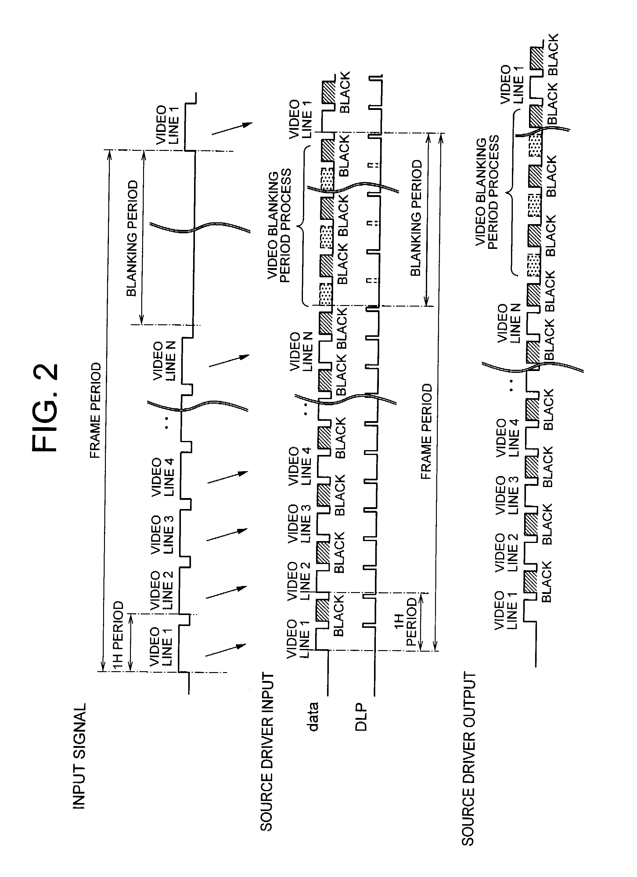
The present invention aims to insert a black screen in one frame period to alleviate moving image blur due to overlap recognition of a current frame image and an afterimage of the previous frame and improve the image quality of the moving image, and to set a black insertion rate with respect to one frame period to a value suited for each usage state. An enable signal (VOE) to each gate driver is independently controlled, and a start pulse (VSP) input to write a black signal is performed at an arbitrary timing within one frame period with respect to the gate driver to insert a black image within one frame period.

Description

CROSS-REFERENCE TO RELATED APPLICATIONS[0001]This application is based upon and claims the benefit of priority from Japanese patent application No. 2007-086190, filed on Mar. 29, 2007, and Japanese patent application No. 2008-039351, filed on Feb. 20, 2008, the disclosure of which is incorporated herein in its entirety by reference.BACKGROUND OF THE INVENTION[0002]1. Field of the Invention[0003]The present invention relates to a hold type image display system.[0004]2. Description of the Related Art[0005]Conventionally, a liquid crystal display (LCD) is generally being widely used since it is thin and does not occupy as much installation area compared to a CRT (Cathode Ray Tube) display. However, in the hold type display device such as LCD, an image continues through a frame period as opposed to an impulse type display device such as CRT display, and thus a moving image tends to become unclear.[0006]In the case of the impulse type display device, an image is displayed as a pulse at a...

Claims


Application Information

Patent Timeline
Patent Type & Authority Applications(United States)
IPC IPC(8): G09G3/36
CPCG09G3/3406G09G3/3648G09G2310/061G09G2320/0261G09G2320/062G09G2320/0633G09G2320/106G09G2340/16
Inventor KIMURA, HIROAKI
Owner NEC LCD TECH CORP
Why Eureka
Try Eureka